
Image generation device, image generation method and non-transitory recording medium storing image generation program

a technology of image generation and image, applied in the direction of instruments, television systems, editing/combining figures or texts, etc., can solve the problem of achieve the effect of reducing the communication load and increasing the communication load on the network

Active Publication Date: 2017-04-20
COLOPL
View PDF13 Cites 23 Cited by
  • Summary
  • Abstract
  • Description
  • Claims
  • Application Information

AI Technical Summary

Benefits of technology

The patent text talks about a virtual space sharing system that sends virtual space information to users over a network, which can be overwhelming for the network. The patent aims to reduce the communication load in this system. The technical effect of this invention is to provide a more efficient and reliable virtual-reality-space sharing system.

Problems solved by technology

This increases the communication load on the network.

Method used


Image

  • Image generation device, image generation method and non-transitory recording medium storing image generation program
  • Image generation device, image generation method and non-transitory recording medium storing image generation program
  • Image generation device, image generation method and non-transitory recording medium storing image generation program

Examples


Embodiment Construction

[0021]Hereinafter, at least one embodiment will be described with reference to the drawings. In the following description, the same parts have the same reference characters allotted. They are named and function in the same manner. Therefore, detailed description thereof will not be repeated.

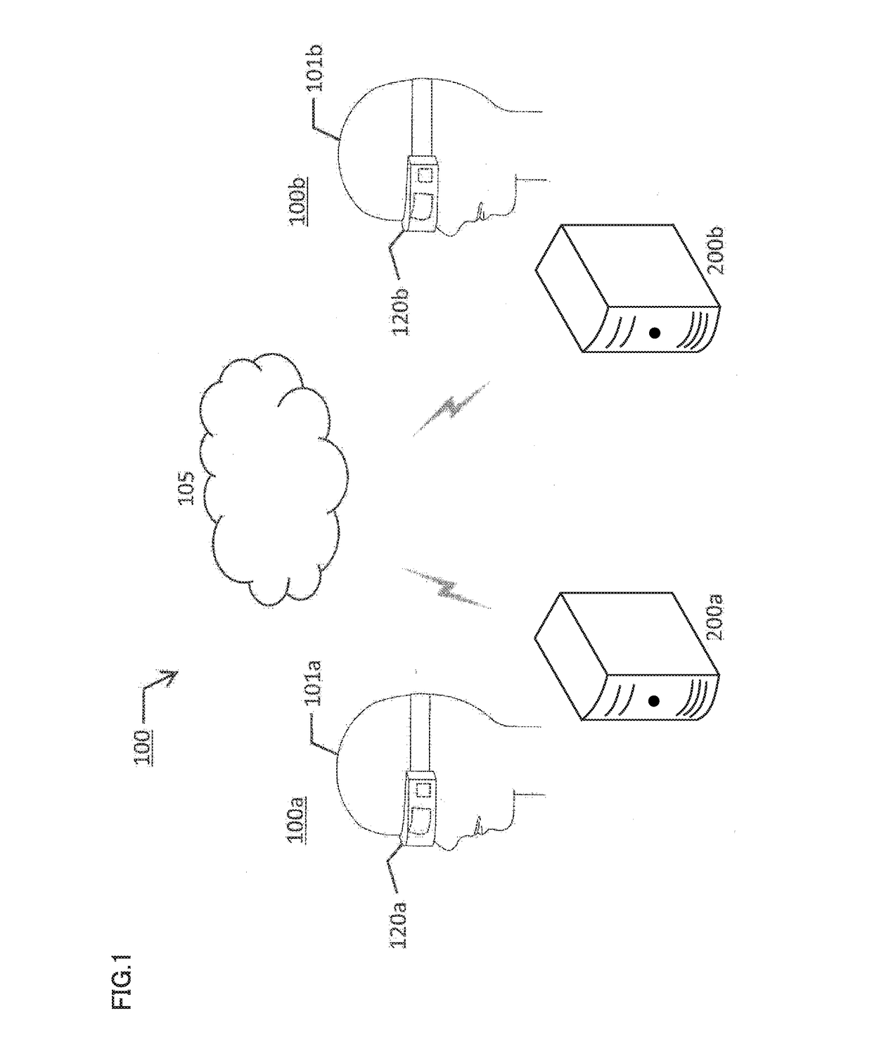
[0022]FIG. 1 is a diagram showing a schematic configuration of virtual-reality-space sharing system 10 according to an embodiment. Virtual-reality-space sharing system 10 includes first subsystem (first terminal) 100a used by a first user 101a and second subsystem (second terminal) 100b used by a second user 101b. First subsystem 100a and second subsystem 100b are connected so as to be capable of communicating with each other over a network 105. Network 105 may be any type of network, such as the Internet or LAN (Local Area Network), for example. While FIG. 1 merely shows two subsystems 100a. and 100b, virtual-reality-space sharing system 10 may include any number of similar subsystems, each bein...


PUM


Abstract

A communication load is reduced in a virtual-reality-space sharing system. An image generation device for generating a virtual reality space image includes a memory for storing an instruction and a processor coupled to the memory for executing the instruction. The instruction, when executed by the processor, causes the processor to acquire, from a second terminal sharing a virtual reality space with a first terminal used by a first user, line-of-sight information including a position and a line-of-sight direction of a second user using the second terminal in the virtual reality space, generate a virtual reality space image to be displayed on the first terminal based on the line-of-sight information acquired from the second terminal, and supply the generated virtual reality space image to the first terminal.

Description

BACKGROUND[0001]Field[0002]The present application claims priority to Japanese Patent Application No. 2015-205476 filed Oct. 19, 2015, the content of which is incorporated by reference herein in its entirety.[0003]The present disclosure relates to an image generation device, an image generation method and an image generation program.[0004]Description of the Related Art[0005]Regarding a head-mounted display, Japanese Patent Laying-Open No. 2002-149581 (Patent Document 1) discloses a technique for “causing a plurality of users to share a virtual space displayed on a head-mounted display, and associating the position of each user in a real space with the position in the virtual space” (see [Abstract]).SUMMARY[0006]According to the virtual space sharing system disclosed in Patent Document 1, however, an information processing server 16 generates virtual space information (image), and transmits the virtual space information to a user control device 15 of each user over a network. This in...

Claims


Application Information

Patent Timeline
IPC IPC(8): G06F3/01G06T11/60H04N5/232G06F3/00
CPCG06F3/013H04N5/23219G06T11/60G06F3/005G06F3/011G06T15/20G06T19/00G06T2219/024G02B27/017G02B2027/0187G02B27/0093H04N23/611
Inventor TERAHATA, SHUHEI
Owner COLOPL
Learn More