
Rebreather control parameter system and dive resource management system

a control parameter and control parameter technology, applied in non-electric variable control, waterborne vessels, instruments, etc., can solve the problems of oxygen toxicity, death of diver, unconscious diver, etc., and achieve the effect of minimizing decompression time and minimizing gas venting

Inactive Publication Date: 2017-04-20
GURR KEVIN +1
View PDF0 Cites 1 Cited by
  • Summary
  • Abstract
  • Description
  • Claims
  • Application Information

AI Technical Summary

Benefits of technology

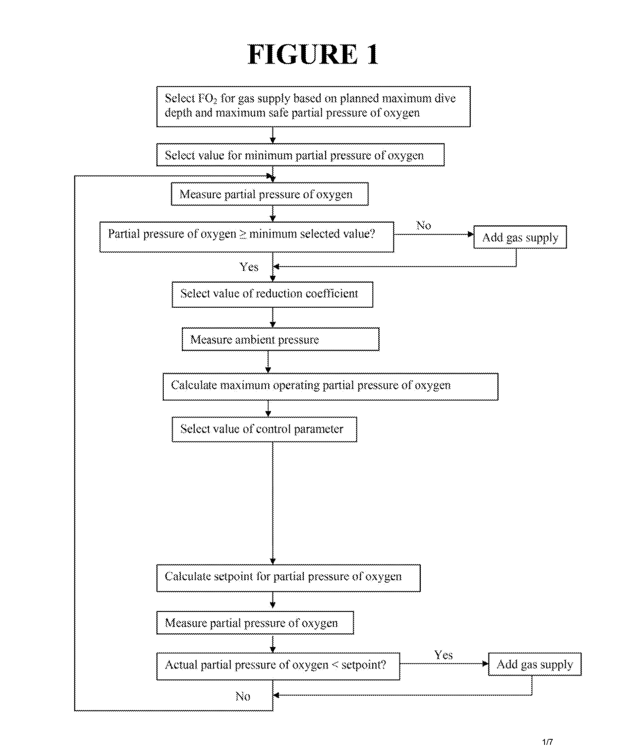
This patent describes a method for controlling the partial pressure of oxygen in a rebreather to adjust the performance of the rebreather between minimizing gas venting and minimizing decompression time. The method involves specifying values for a control parameter, a minimum value of partial pressure of oxygen, a reduction coefficient, and a maximum operating value of partial pressure of oxygen, and calculating a setpoint for partial pressure of oxygen as a function of these values. The method allows for flexibility in setting the partial pressure of oxygen based on the ambient pressure, concentration of oxygen in the gas supply, and the first reduction coefficient. The method can be used with either pure oxygen or an oxygen-enriched gas mixture. The control parameter has a range of 0-100, and the reduction coefficient has a range of 0.75-0.95. The results of this invention include improved safety during diving and better performance of the rebreather.

Problems solved by technology

Open circuit systems are relatively simple and well understood in the art but are inefficient and typically require a large breathing gas supply to provide a reasonable dive time.
Hypoxia can render a diver unconscious and cause drowning.
Hyperoxia may lead to oxygen toxicity, which can have severe physiological effects that can lead to the death of the diver.
However, pulmonary oxygen toxicity can result from prolonged exposure to oxygen partial pressures above approximately 0.5 bar, and CNS oxygen toxicity becomes a significant risk when the partial pressure of oxygen in the breathing loop is greater than 1.6 bar.
However, the rate of addition typically is not automatically adjusted during a dive in response to the actual partial pressure of oxygen in the breathing loop, even though a diver's rate of oxygen consumption, and therefore the oxygen concentration in the breathing loop, may deviate considerably from the rate of consumption estimated prior to the dive.
Inequality between the rate of addition and rate of consumption of oxygen can result in depletion or accumulation of oxygen in the breathing loop.
However, the sensors and automated control systems in closed circuit systems are susceptible to malfunctions, which can lead to hypoxic or hyperoxic oxygen levels in the breathing loop.
Additionally, the use of pure oxygen in closed circuit systems creates handling and cleanliness issues with regard to the breathing gas supply.
A further disadvantage of semi-closed circuit and closed circuit systems is that excessive venting of gas from the breathing loop may occur.
Semi-closed circuit systems are inherently inefficient because the fixed rate of addition of the oxygen-enriched gas mixture to the breathing loop may exceed the diver's rate of oxygen consumption and cause continual venting or purging of gas from the breathing loop to maintain total gas pressure in the breathing loop below a threshold value.
In closed circuit systems, excessive venting may occur during the ascent phase, during which ambient pressure, and correspondingly total gas pressure and partial pressure of oxygen in the breathing loop, decrease.
Additionally, the venting of gas from the breathing loop creates bubbles that may, for example, startle marine life that the diver is attempting to observe, visibly indicate the presence of the diver to observers on the surface or have other undesirable effects.

Method used


Image

  • Rebreather control parameter system and dive resource management system
  • Rebreather control parameter system and dive resource management system
  • Rebreather control parameter system and dive resource management system

Examples


Embodiment Construction

[0038]A rebreather system in accordance with certain embodiments includes a breathing loop comprising a scrubber canister, a counterlung, a sensor for measuring ambient pressure, a pressure transducer for determining depth, a sensor for measuring partial pressure of oxygen in the rebreather breathing loop, a valve for adding a gas supply to the rebreather breathing loop, a power source, connecting hoses, check valves, a processor adapted to receive data, execute calculations, send signals to display data and warning indicators and control the actuation of the addition valve, a gas supply pressure regulator and a gas supply consisting of either a single high-pressure source containing an oxygen-enriched gas mixture or a source containing pure oxygen in conjunction with a source containing diluent gas. In certain embodiments, the rebreather system comprises a passive mechanical addition valve that is adapted to add the gas supply to the rebreather breathing loop at a fixed rate if amb...


PUM


Abstract

A method and apparatus for automatically controlling partial pressure of oxygen in the breathing loop of a rebreather diving system. A diver may adjustably select a control parameter to maintain partial pressure of oxygen at a setpoint that varies with ambient pressure and is within a range between a maximum safe partial pressure of oxygen at depth and a minimum safe partial pressure of oxygen for the purpose of biasing the performance of the rebreather either towards minimizing gas venting from the rebreather breathing loop or minimizing decompression time. A method and apparatus for managing and monitoring the use of dive resources in comparison with a target dive time specified by the diver, calculating and indicating remaining dive time based on dive resource values and calculating and indicating dive resource values required to meet preselected dive resource end values and dive requirements.

Description

CROSS-REFERENCE TO RELATED APPLICATIONS[0001]The present application is a divisional application of U.S. patent application Ser. No. 12 / 862,758 filed on Aug. 25, 2010, which claims the benefit of U.S. Provisional Patent Application No. 61 / 236,426, filed on Aug. 24, 2009, and both disclosures are incorporated herein by reference in their entirety.BACKGROUND[0002]1. Field of the Invention[0003]The present invention relates generally to diving systems and more particularly to systems and apparatuses for controlling and monitoring rebreather systems and managing the use of dive resources.[0004]2. Background Discussion[0005]Self-contained breathing apparatuses used for underwater diving traditionally are categorized either as open circuit systems or rebreather systems. Open circuit systems are relatively simple and well understood in the art but are inefficient and typically require a large breathing gas supply to provide a reasonable dive time. Each breath inhaled by a diver from an ope...

Claims


Application Information

Patent Timeline
Patent Type & Authority Applications(United States)
IPC IPC(8): B63C11/24G05D11/13
CPCB63C11/24B63C2011/188B63C2011/021G05D11/138B63C11/02
Inventor GURR, KEVINBUSHELL, NICHOLAS J.K.
Owner GURR KEVIN
Learn More