
Adjustable burner control valve

a control valve and burner technology, applied in the direction of burner control devices, valve operating means/release devices, lighting and heating apparatus, etc., can solve the problems of pilot light extinguishing or, in some cases, backfir

Active Publication Date: 2017-04-13
EMERSON PROCESS MANAGEMENT REGULATOR TECH INC
View PDF2 Cites 8 Cited by
  • Summary
  • Abstract
  • Description
  • Claims
  • Application Information

AI Technical Summary

Benefits of technology

The patent describes a valve that controls the speed at which fuel is fed to a burner, to prevent the flame from being blown out or coming back into the engine. This valve helps to keep the pilot light steady and steady running.

Problems solved by technology

However, one problem with pneumatic control valves is that the full fuel-gas pressure from the supply of fuel gas is provided to the burner very quickly, which can result in extinguishing of a pilot light or, in some cases, a backfire.

Method used


Image

  • Adjustable burner control valve
  • Adjustable burner control valve
  • Adjustable burner control valve

Examples


Embodiment Construction

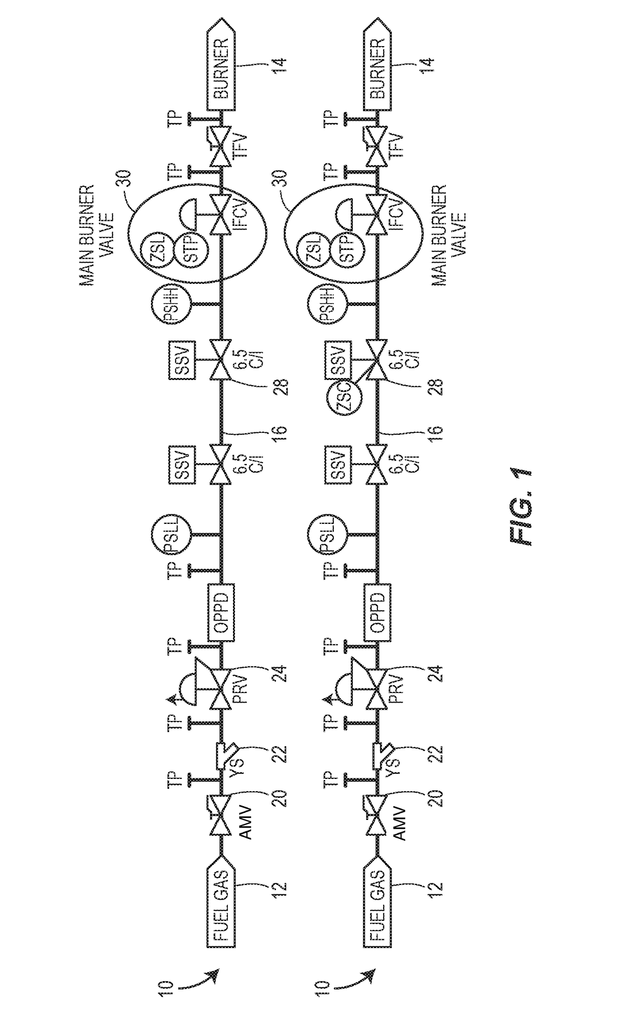
[0012]Turning now to FIG. 1, two fuel-gas burner systems 10 are schematically illustrated. Fuel-gas burner systems 10, such as the systems illustrated in FIG. 1, may be used in the oil and gas industry, or for other industrial uses. For example, such fuel-gas burner systems 10 may be used in heating systems, in dehydrating systems, in flare control systems, or any other system that requires a precise supply of gas to a burner. The fuel-gas burner systems may generally include a source of fuel gas 12 that is connected to a burner 14 by a pipeline 16 or other gas carrying mechanism.

[0013]The fuel-gas burner systems 10 may include various valves and sensors in the pipeline 16 between the source of fuel gas 12 and the burner 14. For example, the fuel-gas burner systems 10 may include one or more of a main valve 20, a y-strainer 22, a pressure reducing regulator 24, a safety shutoff valve 26 and a main burner valve 30. The adjustable burner control valve disclosed herein takes the place ...


PUM


Abstract

A burner control valve with speed control includes a speed control assembly for metering loading pressure into a loading pressure chamber to prevent pilot light blow out and / or backfire in a downstream burner.

Description

FIELD OF THE DISCLOSURE[0001]The disclosure generally relates to burner control valves and more specifically to burner control valves with a speed control mechanism.BACKGROUND OF THE DISCLOSURE[0002]Fuel-gas burner systems are prevalent in the oil and gas industry. Generally fuel-gas burner systems provide heat for use in a system. For example, heat may be used to treat oil or gas during the refining process. In other systems, heat may be used in a dehydrator to evaporate moisture from a liquid or gas. In yet other systems, the heat itself may be a byproduct of disposing of a gas, such as flaring natural gas at an oil well or at a landfill. In some cases, the supply of fuel gas to the burner (or flare) is controlled by a Burner Management System (BMS) that determines when to start or stop the burner. The BMS sends control signals to a control valve to begin and end the supply of fuel gas to the burner. Currently, the control valves are pneumatically operated. Pneumatic control valve...

Claims


Application Information

Patent Timeline
Patent Type & Authority Applications(United States)
IPC IPC(8): F23N1/00F16K31/383
CPCF23N1/007F23D2208/00F16K31/383F16K1/32F16K31/02F16K31/44F16K37/0075F23K5/005F23N1/005F23N2225/14F23N2235/16F23N2235/24
Inventor WEYER, JR., THOMAS L.KOTRAGOUDA BASAPPA, MADHUSUDHAN REDDY
Owner EMERSON PROCESS MANAGEMENT REGULATOR TECH INC
Learn More