Method for measuring the kinematics of at least one turbomachine rotor

a technology of rotors and rotors, which is applied in the direction of speed/acceleration/shock measurement, instruments, and testing of jet-propulsion engines, can solve the problems of poor understanding, difficult to ascertain the precise kinematics of compressors, and few difficulties involved in observing the mechanical behaviour of fundamental engine parts. , to achieve the effect of reducing the risk of an imbalance appearing in operation and limiting the risk of an imbalan

Active Publication Date: 2017-04-06
SN DETUDE & DE CONSTR DE MOTEURS DAVIATION S N E C M A
View PDF2 Cites 0 Cited by
  • Summary
  • Abstract
  • Description
  • Claims
  • Application Information

AI Technical Summary

Benefits of technology

The technology described in this patent is a way to measure the movement of the rotor in an engine without using wired acquisition technologies which have limitations and can cause problems. It uses radioactive tracers that are resistant to shocks and accelerations and can measure the movement of the rotor in all directions. The tracers are evenly distributed around rings which help to prevent imbalances in operation. The rings made of metal and elastic material help to prevent any relative movement between the rotor and the ring during sharp decelerations. The technology can be used during engine development to monitor the movement of the rotor and to gather information about inter-shaft contact, heating, and other events. It is compact and can provide accurate measurements without interfering with the performance of the engine.

Problems solved by technology

However, there are still quite a few difficulties involved in observing the mechanical behaviour of fundamental engine parts.
More specifically, for engine architectures involving deliberate destruction of a low-pressure compressor as a result of buckling during a loss of a blade, it is difficult nowadays to ascertain the precise kinematics of said compressor.
Currently, the poor understanding of the kinematics of the low-pressure compressor, due to a lack of effective means for measuring said kinematics, leads to quite a few conservatisms when designing a turbine engine.
These conservatisms lead to an overestimation of the buckling loads, thus to a local oversizing of the stator and ultimately to an increase in the mass of the turbine engine.
Other phenomena can cause an imbalance, such as during endurance tests of the engine.
In this case, imbalances can appear due to the wear of the parts.
The imbalance which is related to a loss of a fan blade, however, is the most important factor for the stator of a turbine engine.
Currently, there are only very limited technical solutions for measuring the kinematics of a rotor in a test, with digital models as the only option for simulating said kinematics without resetting to actual data.
In addition, the presence of a stator obscures a direct view of the rotating parts and a fortiori prevents direct measurement of the shaft line in one or more planes.
A stator, which is provided with electronic equipment (such as the FADEC, the abbreviation of “full authority digital engine control”), also makes it difficult to put in place a wired acquisition system or to use magnetic sensors, involving the use of a magnetic field.

Method used


Image

  • Method for measuring the kinematics of at least one turbomachine rotor
  • Method for measuring the kinematics of at least one turbomachine rotor
  • Method for measuring the kinematics of at least one turbomachine rotor

Examples


Embodiment Construction

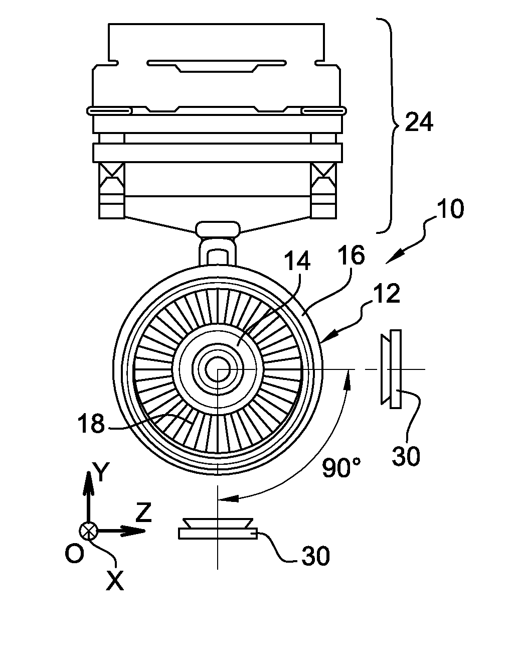
[0034]Reference is firstly made to FIGS. 1A and 1B, which show an installation 10 for implementing the method according to the invention for measuring the kinematics of a rotor of an engine, which in this case is an engine of a propulsion system 12.

[0035]Conventionally, a propulsion system comprises an engine 14 of a turbine engine which is surrounded by a nacelle 16. The engine 14 comprises, from upstream to downstream, in the direction of flow, a fan 18, at least one compressor, a combustion chamber, at least one turbine and a pipe 20 for ejecting combustion gases. The propulsion system 12 is to be connected to a structural element of an aircraft, such as a wing or the fuselage thereof, by means of a strut 22 which is rigidly connected to the engine 14.

[0036]In the case of a turbine engine or a bypass turbojet engine, the engine 14 defines a first annular flow duct for a primary flow or hot flow, and the nacelle 16 defines, around the engine 14, an annular flow duct for a secondar...


PUM


Abstract

The invention relates to a method for measuring the kinematics of at least one rotor of an engine (14), especially a turbomachine, characterised in that the measurement is performed by gamma ray scintigraphy, the method comprising steps consisting in providing the rotor with radioactive tracers, and, during the operation of the engine, detecting the gamma rays emitted by said tracers by means of at least two gamma cameras (30).

Description

TECHNICAL FIELD[0001]The present invention relates to a method for measuring the kinematics of at least one rotor of an engine, in particular of a turbine engine.PRIOR ART[0002]The tests of a turbine engine are carried out either on a rig or in the open air and can be partial or not, i.e. they can involve the entire turbine engine or only a part thereof, such as one of the modules thereof.[0003]One of the objectives of the tests is to collect information about the actual behaviour of the turbine engine or of one of the modules thereof. Thus, the different physical parameters which are relevant for describing the operation of the turbine engine are to be acquired.[0004]The instrumentation technologies and techniques are very diverse in order to measure the physical quantities which govern a turbine engine. However, there are still quite a few difficulties involved in observing the mechanical behaviour of fundamental engine parts.[0005]The main objectives of the overall dynamics are t...

Claims


Application Information

Patent Timeline
Patent Type & Authority Applications(United States)
IPC IPC(8): G01P3/482G01M15/14G01T1/20
CPCG01P3/482G01M15/14G01T1/20
Inventor PETARD, BENJAMIN
Owner SN DETUDE & DE CONSTR DE MOTEURS DAVIATION S N E C M A
Why Eureka
Try Eureka