Control apparatus for electronic parking brake system and control method thereof

a technology of electronic parking brake and control apparatus, which is applied in the direction of braking system, failure to meet the safety requirements of vehicles, braking components, etc., can solve the problems of limiting the reliability of vehicles, and the stability of vehicles that are maintained by conventional esc systems. achieve the effect of improving vehicle reliability and braking efficiency

Active Publication Date: 2017-04-06
HL MANDO CORP
View PDF21 Cites 5 Cited by
  • Summary
  • Abstract
  • Description
  • Claims
  • Application Information

AI Technical Summary

Benefits of technology

[0010]Therefore, it is an aspect of the present disclosure to provide a control apparatus for an electronic parking brake system and a control method thereof capable of improving vehicle reliability as well as braking efficiency.
[0011]It is another aspect of the present disclosure to provide a control apparatus for an EPB system and a control method thereof capable of guiding a driver to be careful with driving while controlling vehicle stopping.
[0012]It is still another aspect of the present disclosure to provide a control apparatus for an EPB system and a control method thereof capable of reducing time required for maintenance of a EPB system to prevent maintenance cost from increasing.

Problems solved by technology

However, conventional ESC systems have shown a limit with maintaining vehicle stability through braking operation when, due to an abnormal operation of the ESC system, a vehicle stopping control function is performed using an automatic stationary vehicle maintaining function such as an automatic vehicle hold (AVH) and hill start assist (HSA).
Due to a limit in stably controlling vehicle stopping with a conventional ESC system, there has been shown a limit to improving braking efficiency and also improving vehicle reliability.

Method used


Image

  • Control apparatus for electronic parking brake system and control method thereof
  • Control apparatus for electronic parking brake system and control method thereof
  • Control apparatus for electronic parking brake system and control method thereof

Examples


first embodiment

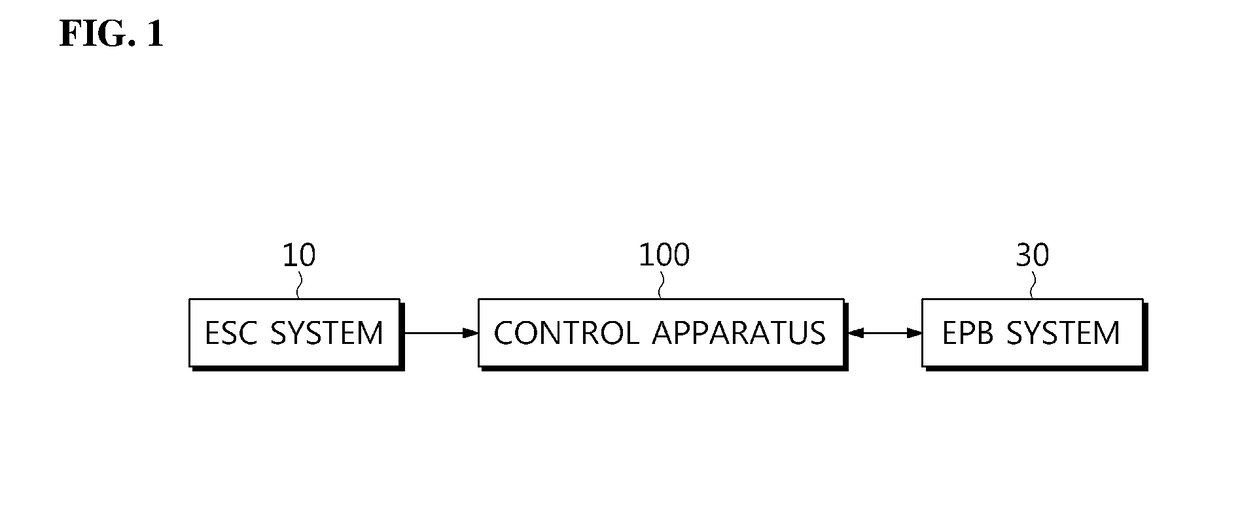
[0043]FIG. 1 is a block diagram illustrating a control apparatus for an electronic parking brake (EPB) system according to the present disclosure, and FIG. 2 is a block diagram illustrating an example of the control apparatus shown in FIG. 1.

[0044]Referring to FIGS. 1 and 2, a control apparatus 100 for the EPB system 30 according to the first embodiment of the present disclosure includes an inputter 102, a determiner 104, and a controller 106.

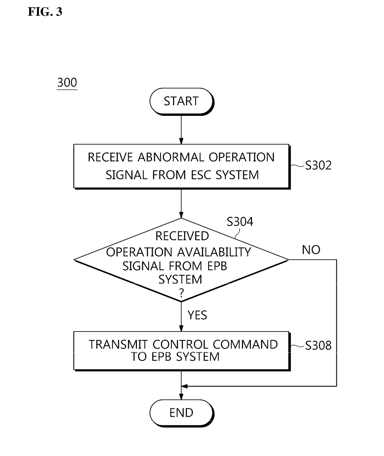
[0045]The inputter 102 receives an abnormal operation signal from an electronic stability control (ESC) system 10 when a vehicle stopping control function is performed in the ESC system 10 due to an abnormal operation.

[0046]Here, the vehicle stopping control function may be automatic stationary vehicle maintaining functions such as an automatic vehicle hold (AVH) and hill start assist (HSA).

[0047]When the determiner 104 receives the abnormal operation signal from the inputter 102, the determiner 104 determines whether an operation availability ...

second embodiment

[0080]FIG. 5 is a block diagram illustrating an example of a control apparatus for an EPB system according to the present disclosure.

[0081]Referring to FIG. 5, a control apparatus 500 for an EPB system 30 according to the second embodiment of the present disclosure includes an inputter 502, a determiner 504, and a controller 506 which are the same as those in the control apparatus 100 (see FIG. 2) for the EPB system 30 (see FIG. 2) according to the first embodiment.

[0082]Since functions of the inputter 502, the determiner 504, and the controller 506, and systematic connection relations therebetween in the control apparatus 500 for the EPB system 30 according to the second embodiment of the present disclosure are the same as the functions of the inputter 102 (see FIG. 2), the determiner 104 (see FIG. 2), and the controller 106 (see FIG. 2), and the systematic connection relations therebetween in the control apparatus 100 (see FIG. 2) for the EPB system 30 (see FIG. 2) according to th...

third embodiment

[0101]FIG. 8 is a block diagram illustrating an example of a control apparatus for an EPB system according to the present disclosure.

[0102]Referring to FIG. 8, a control apparatus 800 for the EPB system 30 according to the third embodiment of the present disclosure includes an inputter 802, a determiner 804, and a controller 806 which are the same as those in the control apparatus 100 (see FIG. 2) for the EPB system 30 (see FIG. 2) according to the first embodiment.

[0103]Since functions of the inputter 802, the determiner 804, and the controller 806, and systematic connection relations therebetween in the control apparatus 800 for the EPB system 30 according to the third embodiment of the present disclosure are the same as the functions of the inputter 102 (see FIG. 2), the determiner 104 (see FIG. 2), and the controller 106 (see FIG. 2), and the systematic connection relations therebetween in the control apparatus 100 (see FIG. 2) for the EPB system 30 (see FIG. 2) according to the...


PUM


Abstract

Disclosed herein are control apparatus for electronic parking brake system and control method thereof. The control apparatus for electronic parking brake system and control method includes an inputter configured to receive an abnormal operation signal from an electronic stability control (ESC) system when a vehicle stopping control function is abnormally performed in the ESC system; a determiner configured to determine whether an operation availability signal of an electronic parking brake (EPB) system is input from the EPB system, when the abnormal operation signal is input; and a controller configured to transmit a control command to the EPB system to activate the EPB system and have the EPB system perform a braking operation, when the operation availability signal of the EPB is input.

Description

CROSS-REFERENCE TO RELATED APPLICATION[0001]This application claims the benefit of Korean Patent Application No. 2015-0140184, filed on Oct. 6, 2015 in the Korean Intellectual Property Office, the disclosure of which is incorporated herein by reference.BACKGROUND[0002]1. Field[0003]Embodiments of the disclosure relate to a control apparatus for an electronic parking brake system and a method thereof.[0004]2. Description of the Related Art[0005]Generally, a conventional electronic stability control (ESC) system is provided to stabilize a vehicle.[0006]However, conventional ESC systems have shown a limit with maintaining vehicle stability through braking operation when, due to an abnormal operation of the ESC system, a vehicle stopping control function is performed using an automatic stationary vehicle maintaining function such as an automatic vehicle hold (AVH) and hill start assist (HSA).[0007]Due to a limit in stably controlling vehicle stopping with a conventional ESC system, ther...

Claims


Application Information

Patent Timeline
Patent Type & Authority Applications(United States)
IPC IPC(8): B60T8/24
CPCB60T8/245B60T2270/30B60T2201/06B60T8/1755B60T8/885B60T7/12B60T7/22B60T8/92B60T2270/40B60T2270/402
Inventor CHOI, HO-JIN
Owner HL MANDO CORP
Why Eureka
Try Eureka