
Common circuit for goa test and eliminating power-off residual images

a goa circuit and residual image technology, applied in the field of liquid crystal display, can solve the problems of limiting analysis and improvement on the goa circuit, improper discharge of electric charges,

Active Publication Date: 2017-03-30
WUHAN CHINA STAR OPTOELECTRONICS TECH CO LTD
View PDF3 Cites 9 Cited by
  • Summary
  • Abstract
  • Description
  • Claims
  • Application Information

AI Technical Summary

Benefits of technology

The present invention is a common circuit that can test the output signals of the different stages of a gate-on-array (GOA) circuit to determine where the malfunction is located. It also helps to eliminate power-off residual images by discharging the residual electric charge of the liquid crystal and storage capacitors. Compared to existing techniques, this invention has the advantage of being able to test the output signals of any stage of the GOA circuit.

Problems solved by technology

When powered off, the accumulated electric charges do not receive proper release, resulting in DC residual in the liquid crystal molecules to cause residual images on the LCD panel, often referred to as power-off residual images.
However, this type of test can only test the output signal of the final GOA unit, and is unable to determine specifically which stage of GOA unit is faulty, which limits the analysis and improvement on the GOA circuit.

Method used


Image

  • Common circuit for goa test and eliminating power-off residual images
  • Common circuit for goa test and eliminating power-off residual images
  • Common circuit for goa test and eliminating power-off residual images

Examples


first embodiment

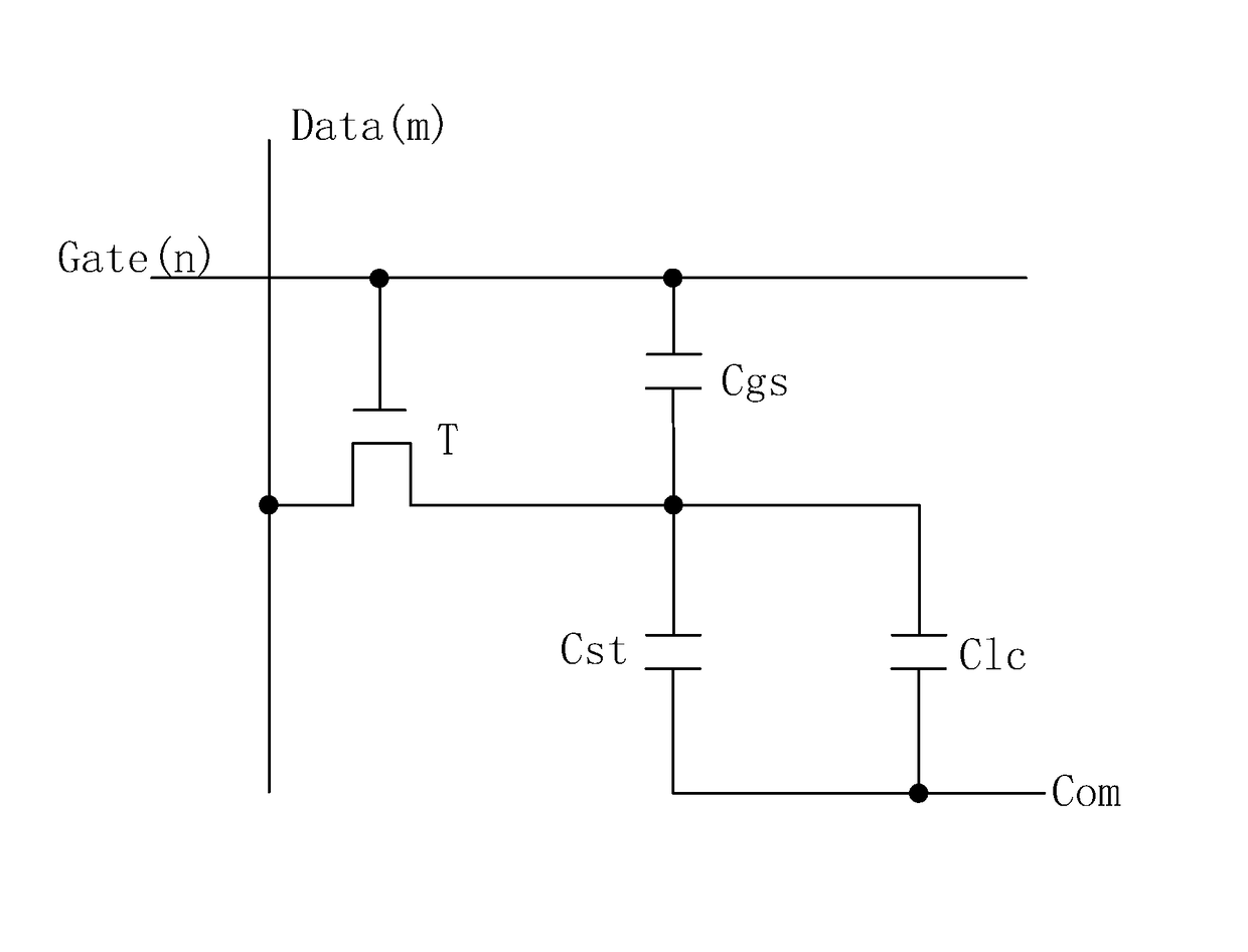
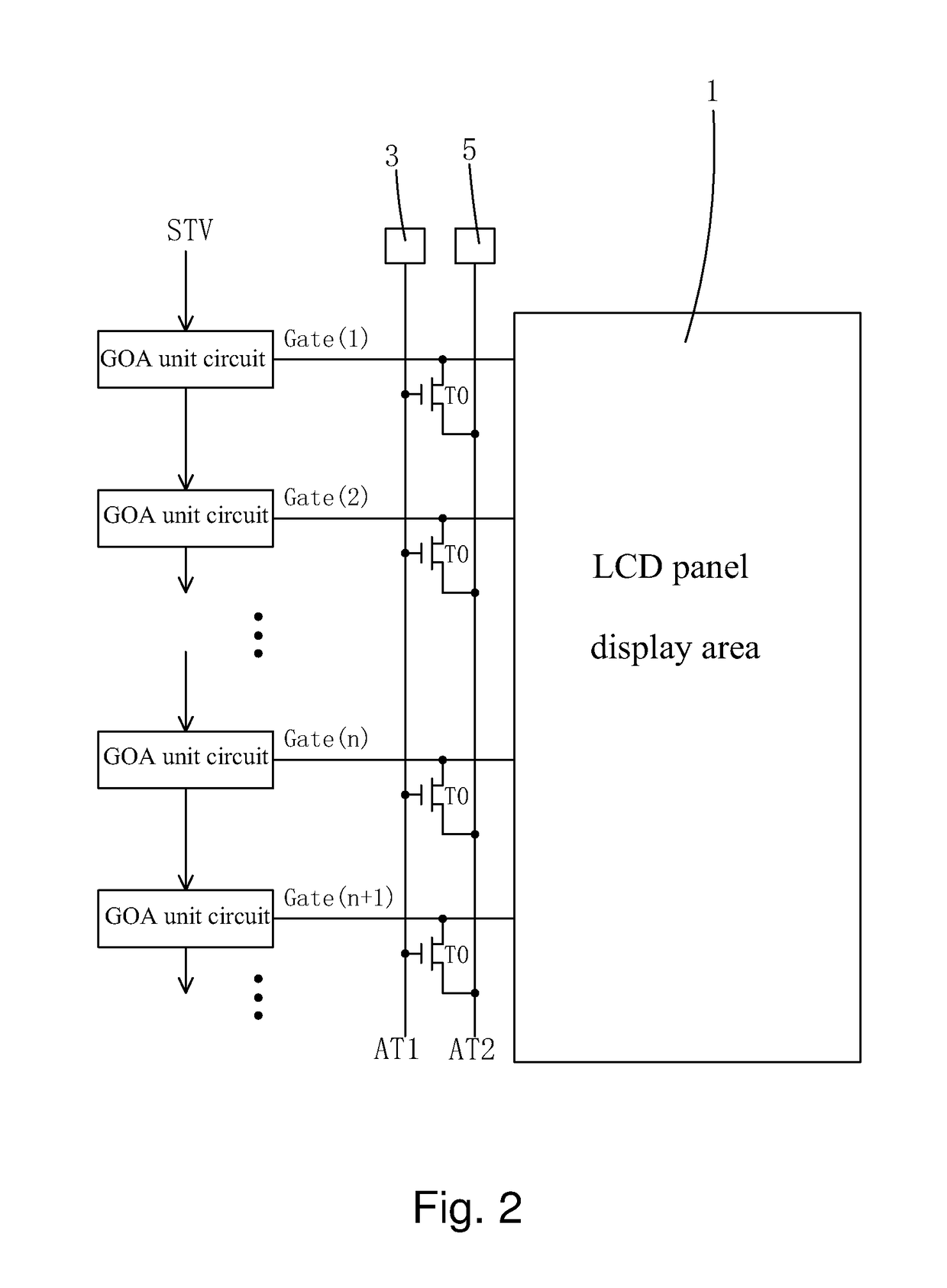
[0027]The present invention provides a common circuit for GOA test and eliminating power-off residual images. FIG. 2 is a schematic view showing the common circuit for GOA test and eliminating power-off residual image provided by an embodiment of the present invention, including a plurality of cascade GOA unit circuits, disposed at a side of a display area 1 of an LCD panel, for a positive integer n, an output end of n-th stage GOA unit circuit connected to a corresponding n-th gate scan line Gate(n) of the LCD panel; a first test end 3, disposed at a side of the display area 1 of the LCD panel; a second test end 5, disposed at a side of the display area 1 of the LCD panel; a test signal line AT1, disposed at a side of the display area 1 of the LCD panel and electrically connected to the first test end 3; a feedback signal line AT2, disposed at a side of the display area 1 of the LCD panel and electrically connected to the second test end 5; and the same number of test TFTs T0 as th...

second embodiment

[0036]The second embodiment disposes a plurality of cascade GOA unit circuits, the first test end 3, the second test end 5, the test signal line AT1 the feedback signal line AT2, and a plurality of test TFTs in both sides of the display area 1 of the LCD panel, and thus is suitable for testing double-sided double-driver GOA circuit, and double-sided double-driver GOA circuit.

[0037]In summary, the common circuit for GOA test and eliminating power-off residual images of the present invention comprises a first test end, a test signal line electrically connected to the first test end, a second test end, a feedback signal line electrically connected to the second test end, and a plurality of test TFTs having the same number as the number of cascade GOA unit circuits. By connecting the gate of each test TFT to the test signal line, the source to the feedback signal line and the drain to the output end of corresponding GOA unit circuit and corresponding gate scan line, the present inventio...


PUM


Abstract

The invention discloses a common circuit for GOA test and eliminating power-off residual images, including a first test end (3), a test signal line (AT1) connected to the first test end (3), a second test end (5), a feedback signal line (AT2) connected to the second test end (5), and the same number of test TFTs (T0) as cascade GOA unit circuits. By connecting the gate of each test TFT (T0) to test signal line (AT1), the source to feedback signal line (AT2) and the drain to the output end of corresponding GOA unit circuit and gate scan line, the invention can test the output signal of any stage GOA unit circuit to determine the location of a malfunctioning GOA unit circuit, and releasing the residual charges of the liquid crystal capacitor and storage capacitor at the display area of LCD panel when powering off to eliminate residual images.

Description

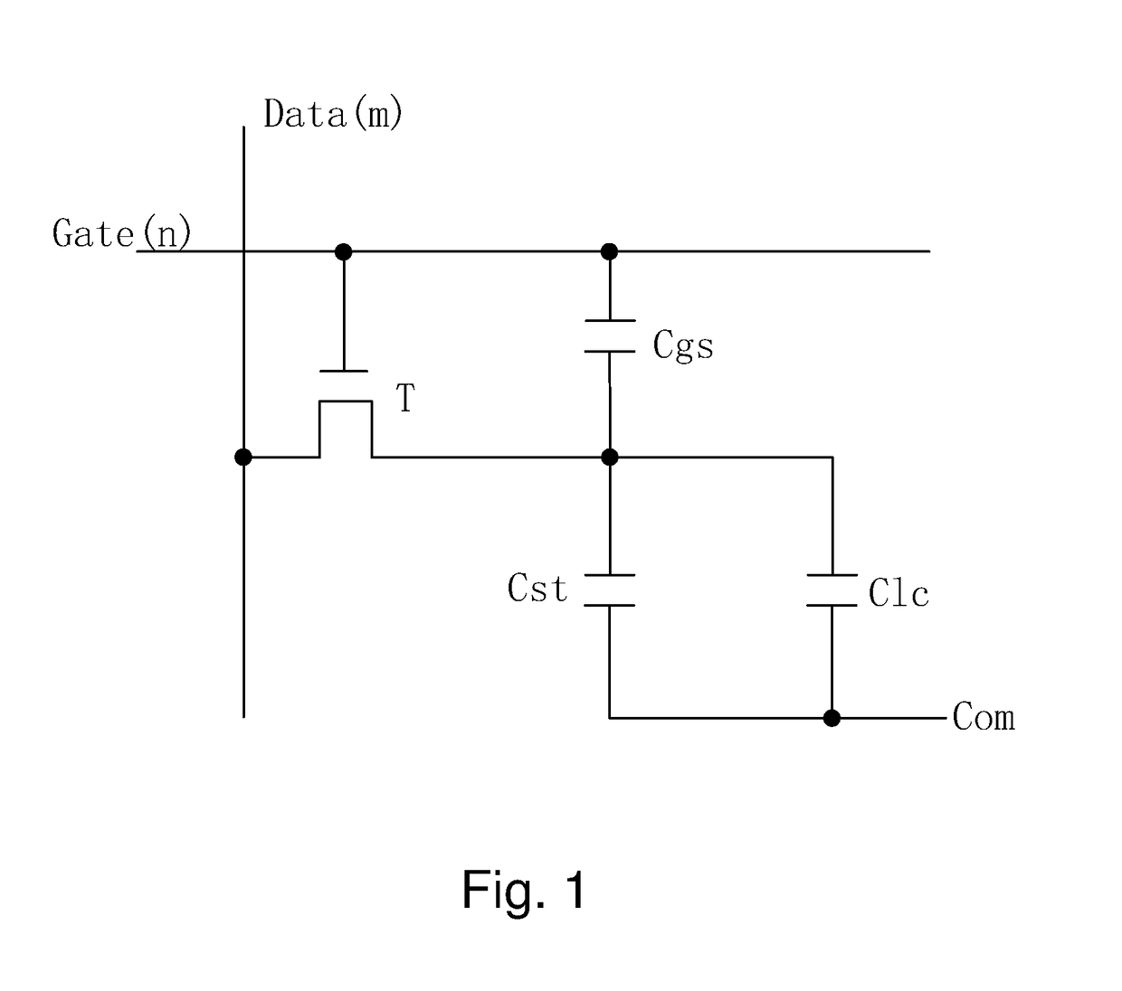
BACKGROUND OF THE INVENTION[0001]1. Field of the Invention[0002]The present invention relates to the field of liquid crystal display (LCD), and in particular to a common circuit for gate driver on array (GOA) test and eliminating power-off residual images.[0003]2. The Related Arts[0004]As the liquid crystal display (LCD) shows the advantages of being thin, low power-consumption, and no radiation, the LCD is widely used in various devices, such as, liquid crystal TV, mobile phones, PDA, digital camera, PC monitors or notebook PC screens as well as tablet PCs.[0005]The available LCDs are mostly backlight type, which includes an LCD panel and a backlight module. The operation theory behind the LCD panel is to inject liquid crystal molecules between the thin film transistor (TFT) array substrate and the color filter (CF), and then apply a driving voltage to control the rotation direction of the liquid crystal molecules to refract the light from the backlight module to generate the image...

Claims


Application Information

Patent Timeline
Patent Type & Authority Applications(United States)
IPC IPC(8): G09G3/36G09G3/18
CPCG09G3/18G09G3/3611G09G3/006G09G3/3677G09G2300/0408
Inventor CAO, SHANGCAO
Owner WUHAN CHINA STAR OPTOELECTRONICS TECH CO LTD
Learn More