
Compressor endwall treatment to delay compressor stall

Active Publication Date: 2017-03-30
GENERAL ELECTRIC CO
View PDF1 Cites 0 Cited by
  • Summary
  • Abstract
  • Description
  • Claims
  • Application Information

AI Technical Summary

Benefits of technology

The patent describes a compressor with an endwall treatment to prevent compressor stall caused by ice ingestion. The endwall treatment is formed in the compressor's casing and includes a tip facing each blade in the compressor stages. The tip and the endwall treatment move relative to each other. The remaining stages of the compressor stages not located between the two most downstream stages are devoid of any endwall treatment. The endwall treatment is designed to extend a stall margin and delay stall caused by ice ingestion. The technical effect of this invention is to improve the compressor's performance and reliability in extreme conditions where ice cannot be avoided.

Problems solved by technology

When engines operate in icing conditions, ice may accumulate on the low pressure compression system of the engine.
More specifically, if such engines are operated within icing conditions at low power for extended periods of time, ice accumulation within the engine may be significant.
Accumulated ice in low pressure compression system may shed and enter high pressure compression system and cause compressor instability including compressor surge, partial or total thrust loss, or power roll-backs with little or virtually no warning.
This results in reduced compressor capability to compress air and hence reduction in overall thrust generated by turbine.
This results in increased compressor stall margin and delays a stall event resulting in undesirable thrust loss.
However, such attempts may significantly increase complexity and weight of the compressor.
Early attempts on such endwall treatments have a substantial impact on design point efficiency with very minimal benefit in delaying the stall margin of the compressor.

Method used


Image

  • Compressor endwall treatment to delay compressor stall
  • Compressor endwall treatment to delay compressor stall
  • Compressor endwall treatment to delay compressor stall

Examples


Embodiment Construction

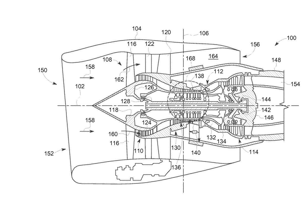
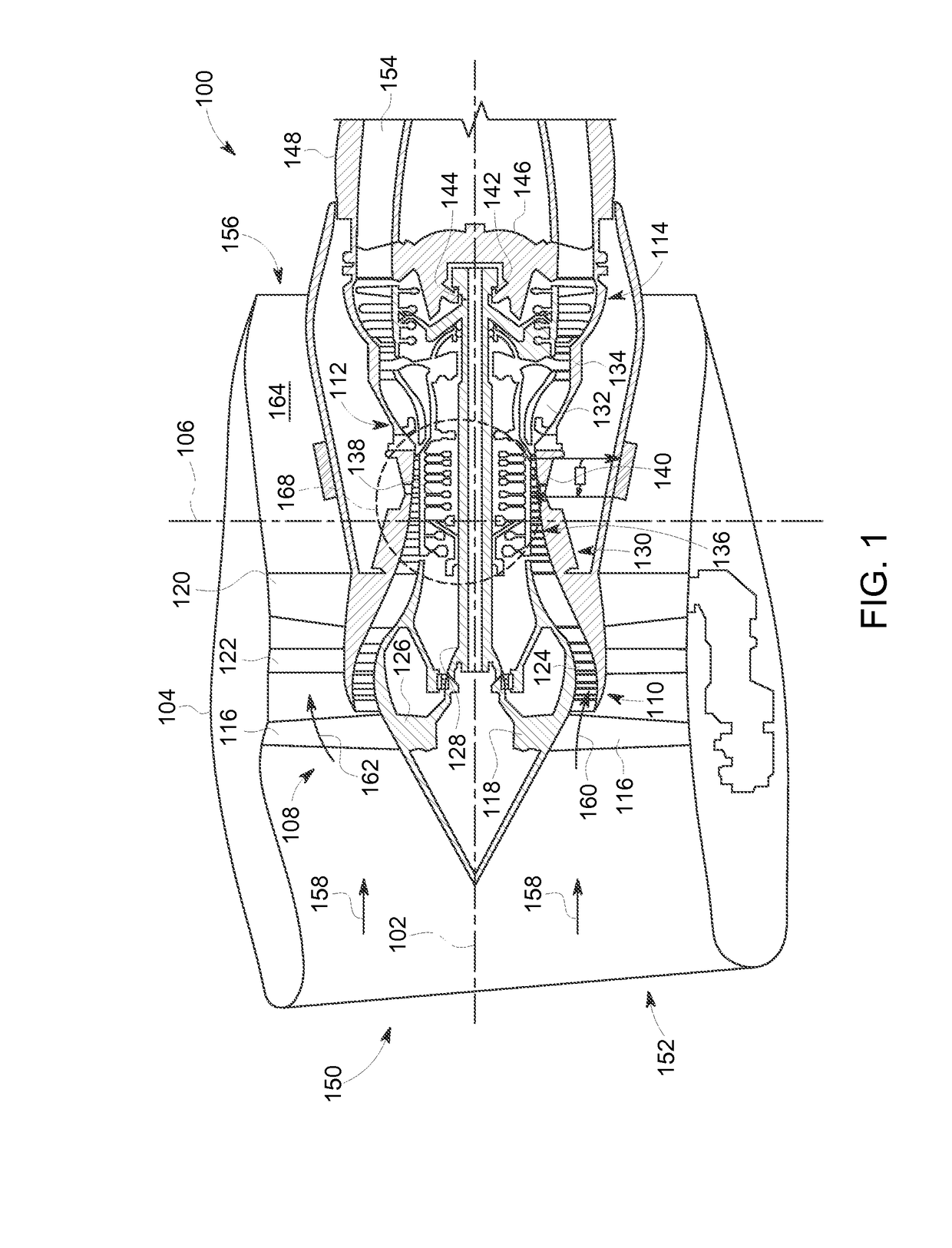
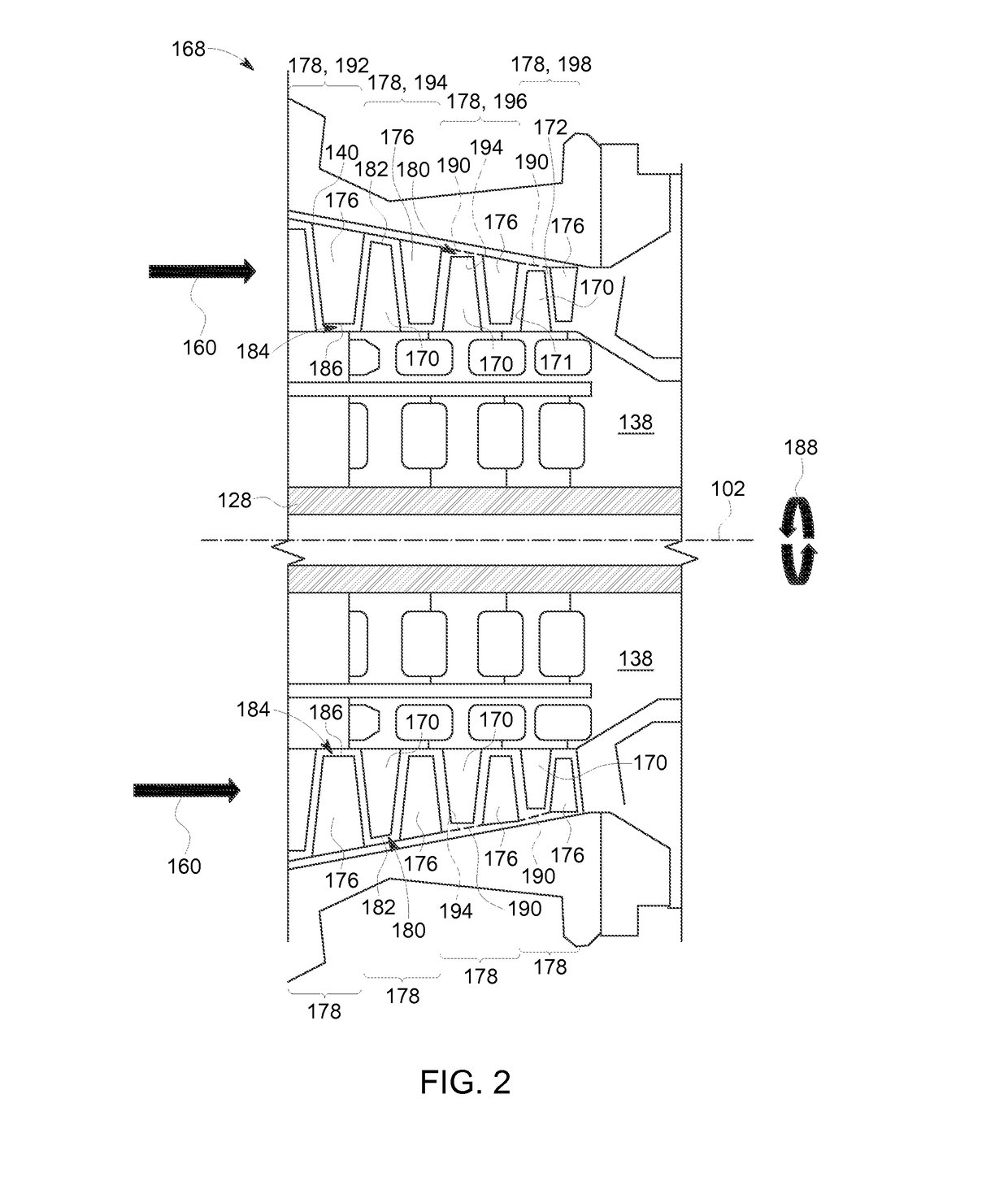
[0019]Embodiments discussed herein disclose an improved compressor for deployment in engines such as a gas turbine, a steam turbine, and the like. The compressor may be an axial flow compressor and according to one embodiment such compressor includes an endwall treatment on selected downstream compressor stages, and in particular on at least two downstream most stages, and wherein the remaining stages of a plurality of compressor stages located upstream of the at least two downstream most stages are devoid of any endwall treatment to allow the compressor to operate with larger amount of ingested water / ice / hail as compared to baseline geometry and thus delaying and improving a stall margin with minimal penalty on design point efficiency of the compressor. In one embodiment of the present disclosure such endwall treatment on the at least two downstream / rear compressor stages is formed in a casing of the compressor, and faces a tip of each blade among a plurality of blades positioned i...


PUM


Abstract

A compressor is provided including a casing, a hub, a flowpath, a plurality of blades defining a plurality of axially extending compressor stages and an endwall treatment formed in the casing on at least two downstream most stages of the plurality of compressor stages. The remaining stages of the plurality of compressor stages located upstream of the at least two downstream most stage are devoid of any endwall treatment. Each of the endwall treatments faces a tip of each blade in the at least two downstream most stages. The tip of each blade and the endwall treatment are configured to move relative to each other. The endwall treatment formed in the casing on at least two downstream most stages of the plurality of compressor stages is configured to extend a stall margin to delay stall due to ice ingestion. A method and engine application are disclosed.

Description

BACKGROUND[0001]The present invention relates to a compressor, and more particularly to an endwall treatment disposed in a casing of such compressor to provide a delay in compressor stall.[0002]Compressors used in engines such as a gas turbine, may include a plurality of stages arranged along a length of the compressor. Each stage may include a hub and a plurality of rotor blades arranged about a circumference of the hub. In addition, each stage may further include a plurality of stator blades, disposed alternately to the plurality of rotor blades and arranged about a circumference of a casing of the compressor.[0003]During operation of such gas turbine, the hub of the compressor may be rotated at high speed by a turbine, such that a fluid is continuously induced into the compressor. The fluid is accelerated by the rotating rotor blades and swept rearwards onto the adjacent rows of the stator blades. At each stage, the rotor blade and / or stator blade increases pressure of the fluid....

Claims


Application Information

Patent Timeline
IPC IPC(8): F01D25/02F02C3/04
CPCF01D25/02F05D2220/32F02C3/04F04D29/526F05D2250/294F05D2220/3219F04D17/122F04D29/685F04D27/02
Inventor SAXENA, SWATIBREEZE-STRINGFELLOW, ANDREWSINGH, RAJKESHAR VIJAYRAJNAKANO, TSUGUJI
Owner GENERAL ELECTRIC CO
Learn More