
Method for characterizing the fracture network of a fractured reservoir and method for exploiting it

Active Publication Date: 2017-03-16
INST FR DU PETROLE
View PDF0 Cites 21 Cited by
  • Summary
  • Abstract
  • Description
  • Claims
  • Application Information

AI Technical Summary

Benefits of technology

The present invention is a method for exploiting a fluid within an underground formation. The method involves constructing a gridded representation of the formation layers, measuring statistical parameters of the fracture network, and defining zones of interest. An equivalent permeability tensor and a parameter characterizing the orientation and continuity of the fractures are determined for each zone. A simplified fracture network model is then determined for each zone, and an optimum exploitation scheme is defined based on the model, statistical parameters, and predetermined techno-economic criteria. The method can be implemented using a computer program product. The technical effects of the invention include improved understanding and exploitation of fractured formations, improved well placement, and increased production efficiency.

Problems solved by technology

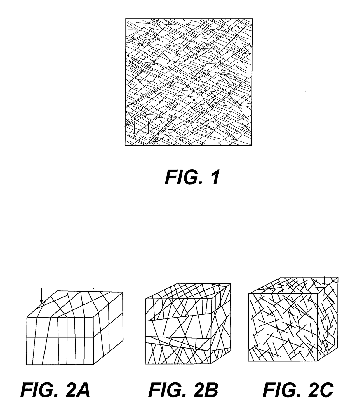
However, this method is only suited for fracture networks substantially orthogonal to the layers and continuous from one layer to another, i.e. fracture networks whose flow behaviour is comparable to a 2D behaviour (see notably patent applications FR-2,530,493 (U.S. Pat. No. 9,103,194) and FR-2,581,767 (U.S. Ser. No. 13 / 644,479), as well as document (Fourno et al., 2013)).
However, these methods remain prohibitive today in terms of computation time, notably when a large number of flow simulations (at reservoir scale or at the scale of a zone of influence of one or more wells) is required (case of production scheme optimization, production history matching or calibration of the statistical parameters of fracture families using parameter sensitivity procedures).

Method used


Image

  • Method for characterizing the fracture network of a fractured reservoir and method for exploiting it
  • Method for characterizing the fracture network of a fractured reservoir and method for exploiting it
  • Method for characterizing the fracture network of a fractured reservoir and method for exploiting it

Examples


application example

[0194]The features and advantages of the method according to the invention will be clear from reading the application example hereafter.

[0195]The present invention is applied to an underground formation consisting of a single layer traversed by five wells, the layer containing a hydrocarbon type fluid and a fracture network wherein at least the orientation of one family leads to a parameter value P equal to 0 (3D type fracture network).

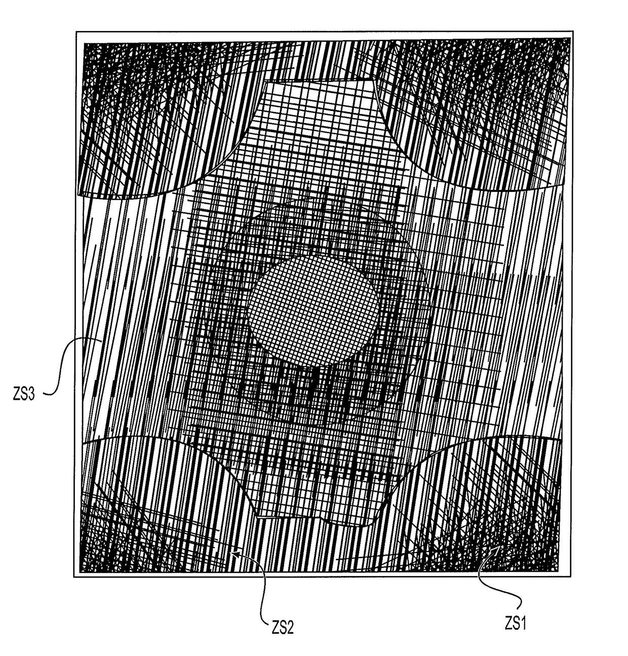
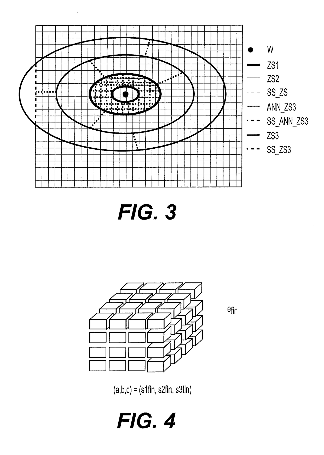
[0196]The goal of this application is to determine the optimum exploitation scheme, i.e. an exploitation scheme allowing optimum hydrocarbon recovery while meeting techno-economic constraints. Among the exploitation schemes evaluated by flow simulation, a conventional exploitation scheme of five-spot injection type, with an injection well in the centre of the formation to be exploited and four wells on the periphery, has been tested. Three simplification zones ZS1, ZS2, ZS3 of circular geometry have been defined around each well and for each layer of ...


PUM


Abstract

Method for exploiting a fluid within an underground formation comprising a layer traversed by a fracture network and a well.From property measurements relative to the layer, the fracture network is characterized by statistical parameters and a discrete fracture network model is constructed. For each well, three simplification zones surrounding the well are defined. From the statistical parameters, an equivalent permeability tensor and a parameter characterizing the orientation and the vertical continuity of the fractures are determined for each zone. For each zone, a simplification of the discrete fracture network model is determined as a function of the zone, the equivalent permeability tensor and the value of the parameter. An optimum exploitation scheme is defined for the formation fluid from the simplified fracture network model and a flow simulator.Application: notably petroleum exploration and exploitation.

Description

FIELD OF THE INVENTION[0001]The present invention relates to the petroleum industry, and more specifically to the exploration and exploitation of hydrocarbon reservoirs or of geological gas storage sites.[0002]In particular, the invention relates to a method for constructing a representation of an underground formation traversed by any fracture network and to the use of this representation for simulation of the fluid flows in the formation considered.BACKGROUND OF THE INVENTION[0003]Exploration and exploitation of reservoirs, notably petroleum reservoirs, require knowledge of the underground geology as perfect as possible so as to efficiently provide reserves evaluation, production modelling or exploitation management. Indeed, determining the location of a production well or of an injection well within a hydrocarbon reservoir, the drilling mud composition, the completion characteristics, selection of a hydrocarbon recovery method (such as waterflooding for example) and of the parame...

Claims


Application Information

Patent Timeline
IPC IPC(8): G01N15/08E21B41/00E21B43/14
CPCG01N15/082E21B41/0092E21B43/14E21B41/00E21B49/00G01V99/00
Inventor FOURNO, ANDREBOURBIAUX, BERNARD
Owner INST FR DU PETROLE
Learn More