Method and device for manufacturing a tubular lagging element from sheet metal

Active Publication Date: 2017-03-16
INTERVER MANAGEMENT
View PDF2 Cites 0 Cited by
  • Summary
  • Abstract
  • Description
  • Claims
  • Application Information

AI Technical Summary

Benefits of technology

The disclosure proposes a method and machine that can automate the rolling and molding processes into a single operation. This results in parts that have a high level of quality and consistency. The disclosure also aims to reduce the time and effort required for manufacturing and adjusting the machine settings. Additionally, it seeks to eliminate the over-rolling and under-rolling effect.

Problems solved by technology

According to the prior art, shaping of the ends of the heat-insulating elements is performed after said element has been given its cylindrical shape by rolling and pre-assembly of its longitudinal edges, so causing the problems mentioned above.

Method used


Image

  • Method and device for manufacturing a tubular lagging element from sheet metal
  • Method and device for manufacturing a tubular lagging element from sheet metal
  • Method and device for manufacturing a tubular lagging element from sheet metal

Examples


Embodiment Construction

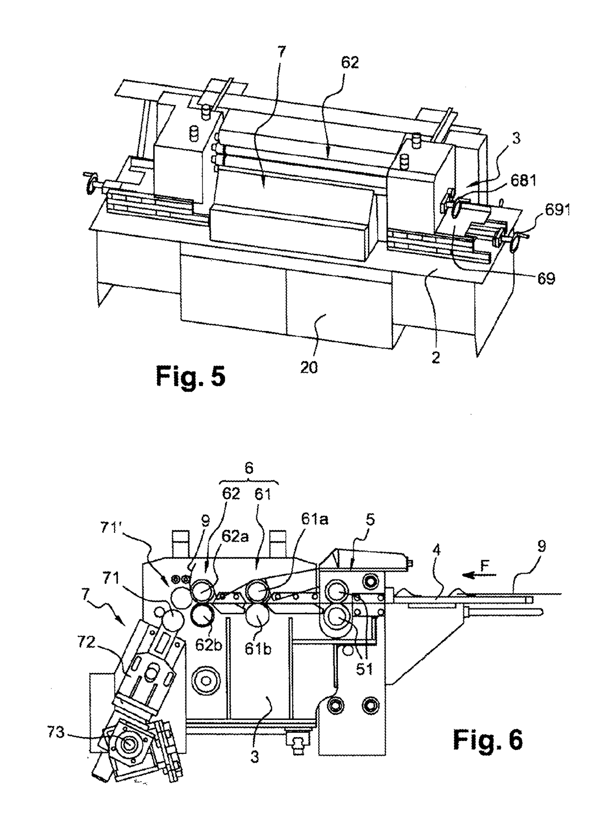
[0047]The machine according to an embodiment of the invention shown in FIG. 5 comprises a base 2 mounted on castors and provided with a casing 20 holding the shaping rollers, and a frame 3 ensuring the rigidity of the machine, placed on the base 2.

[0048]The machine further comprises:[0049]a feed table 4 supported on the frame 3,[0050]a drive unit 5,[0051]a set of shaping rolls 6,[0052]a roll-bending unit 7.

[0053]The drive unit 5 comprises a set of motorized pinch rolls 51 for gripping the blanks deposited on the feed table 4 and driving them in the direction of travel, according to the arrow F, towards the set of shaping rolls 6.

[0054]The set of shaping rolls 6 comprises two sets of shaping rolls: one set 61 of rough-machining rolls 61a, 61b and one set 62 of finishing rolls 62a, 62b. All these rolls are motorized. Each shaping roll comprises a cylindrical central roll 63, the ends of which are mounted, connected for rotation, on driving half-shafts 64 which also bear, adjacent the ...


PUM

PropertyMeasurementUnit
Thicknessaaaaaaaaaa
Lengthaaaaaaaaaa

Abstract

The apparatus for manufacturing a tubular, sheet metal heat-insulating element (1) from a sheet metal blank (9) successively comprises, in a direction of travel perpendicular to the axis of the heat-insulating element to be produced, a drive unit (5) for conveying the blank (9) flat in the direction of travel (F), a set of shaping rolls (61, 62) comprising shaping rollers (65, 66) for forming a relief on the edge of the blank, and a roll-bending unit (7), situated immediately downstream of the set of shaping rolls, for roll-bending the blank comprising said relief. Firstly, reliefs are shaped on the edges of the blank by means of shaping rolls, then roll-bending is performed, preferably immediately thereafter and in the same operation, the edge-forming and roll-bending being carried out in a single pass.

Description

TECHNICAL FIELD[0001]The present invention relates to a method and a device for manufacturing tubular, sheet-metal heat-insulating elements that will be designated hereinafter also as pipes or shells.BACKGROUND[0002]Such elements, typically cylindrical in form and of lengths of the order of 1000 or 1250 mm, commonly also known as “sections”, are used for heat insulation of heat-transfer fluid ducts. They consist of a punched rectangular sheet-metal blank, which is then roll-bent, remaining open along a generating line, so as to be capable of lateral insertion around the duct to be heat-insulated. The two opposing longitudinal edges are then joined together, by means of machine bolts for example. Furthermore, the axial ends of these heat-insulating elements are shaped such that the elements can be fitted together by push-fitting. The general principle used for fitting together in a straight line is push-fitting using male and female moldings, this push-fit being capable of ensuring g...

Claims


Application Information

Patent Timeline
IPC IPC(8): B21D5/14B21D5/12B21D53/06B21C37/08
CPCB21D5/14B21D53/06B21D5/12B21C37/0815B21C37/083B21D17/04F16L9/17F16L37/02B21D5/00
Inventor VANDEVELDE, PIERRE
Owner INTERVER MANAGEMENT
Why Eureka
Try Eureka