
Variable nozzle unit and variable geometry turbocharger

a variable geometry, nozzle technology, applied in the direction of machines/engines, engine manufacture, combustion engines, etc., can solve the problems of reducing the turbine efficiency difficulty in ensuring the reliability of the variable geometry turbocharger, maintaining or improving the turbine efficiency, etc., to achieve the effect of reducing the thermal deformation of the first wall member, preventing the thermal deformation of the nozzle side, and maintaining the stability of the multiple variable nozzl

Active Publication Date: 2017-03-02
IHI CORP
View PDF5 Cites 13 Cited by
  • Summary
  • Abstract
  • Description
  • Claims
  • Application Information

AI Technical Summary

Benefits of technology

This patent relates to a variable nozzle unit for a turbocharger. The technical effects of this patent are that it contributes to improving turbine efficiency and ensuring reliability of the turbocharger. The invention synchronizes the operation of multiple variable nozzles to increase the gas passage area for supplying exhaust gas to the turbine wheel. It also absorbs any thermal deformation through an absorbing unit to prevent the nozzle from tilting and minimize leakage flow, thus maintaining or improving the turbine efficiency of the turbocharger.

Problems solved by technology

In the meantime, when the nozzle side clearance is set larger, turbine efficiency of the variable geometry turbocharger tends to decrease because of an increase in leakage flow from the nozzle side clearance.
In other words, there is a problem of difficulty in ensuring the reliability of the variable geometry turbocharger and maintaining or improving the turbine efficiency of the variable geometry turbocharger with at the same time.

Method used


Image

  • Variable nozzle unit and variable geometry turbocharger
  • Variable nozzle unit and variable geometry turbocharger
  • Variable nozzle unit and variable geometry turbocharger

Examples


modified example of embodiment

of Present Disclosure

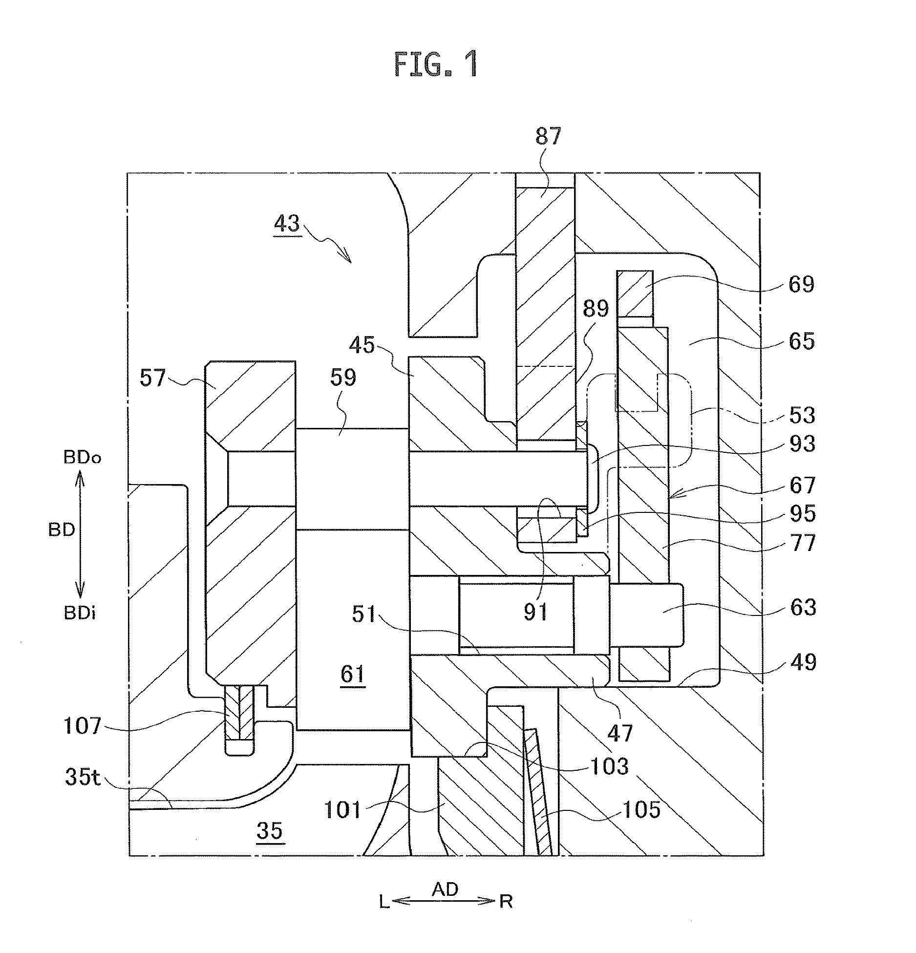
[0063]Instead of using the support ring 87 (see FIG. 1) as the constituent of the variable nozzle unit 43 (see FIG. 1), a different support ring 87A may be used as shown in FIG. 8. The support ring 87A has a configuration similar to that of the support ring 87. A description will be given below only of portions of a configuration of the support ring 87A which are different from those of the configuration of the support ring 87. Note that elements among multiple constituents in the support ring 87A which correspond to the elements among those in the support ring 87 will be denoted by the same reference signs in the drawings.

[0064]As shown in FIG. 8, FIGS. 9A and 9B, and FIG. 10A, regarding the support ring 87A, each pin hole 91 in the support ring 87A is formed into a round hole. In addition, a slit 109 for absorbing a difference in thermal expansion in a radial direction, which is attributed to a difference in ambient temperature (a difference in ambient gas tem...


PUM


Abstract

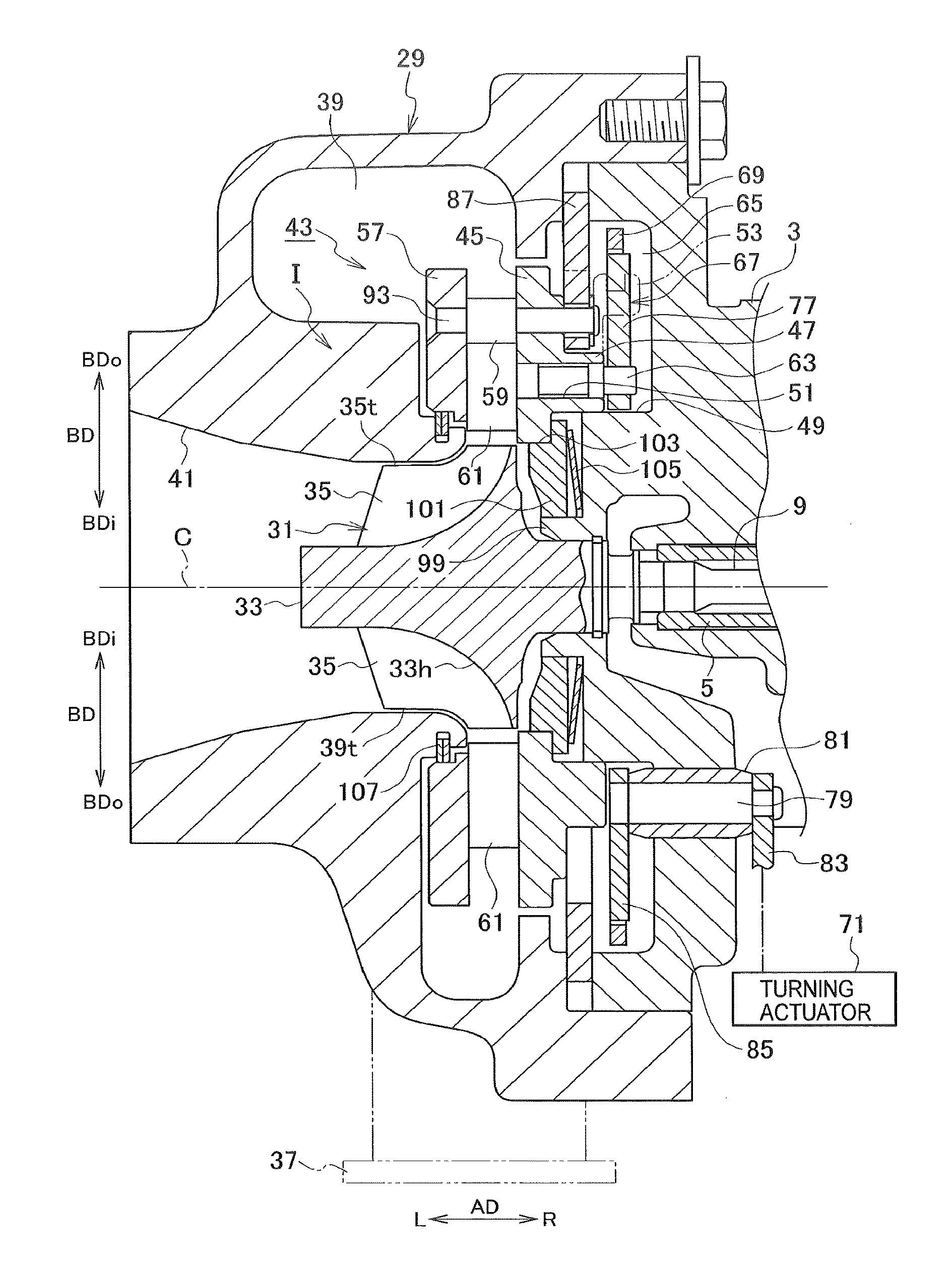
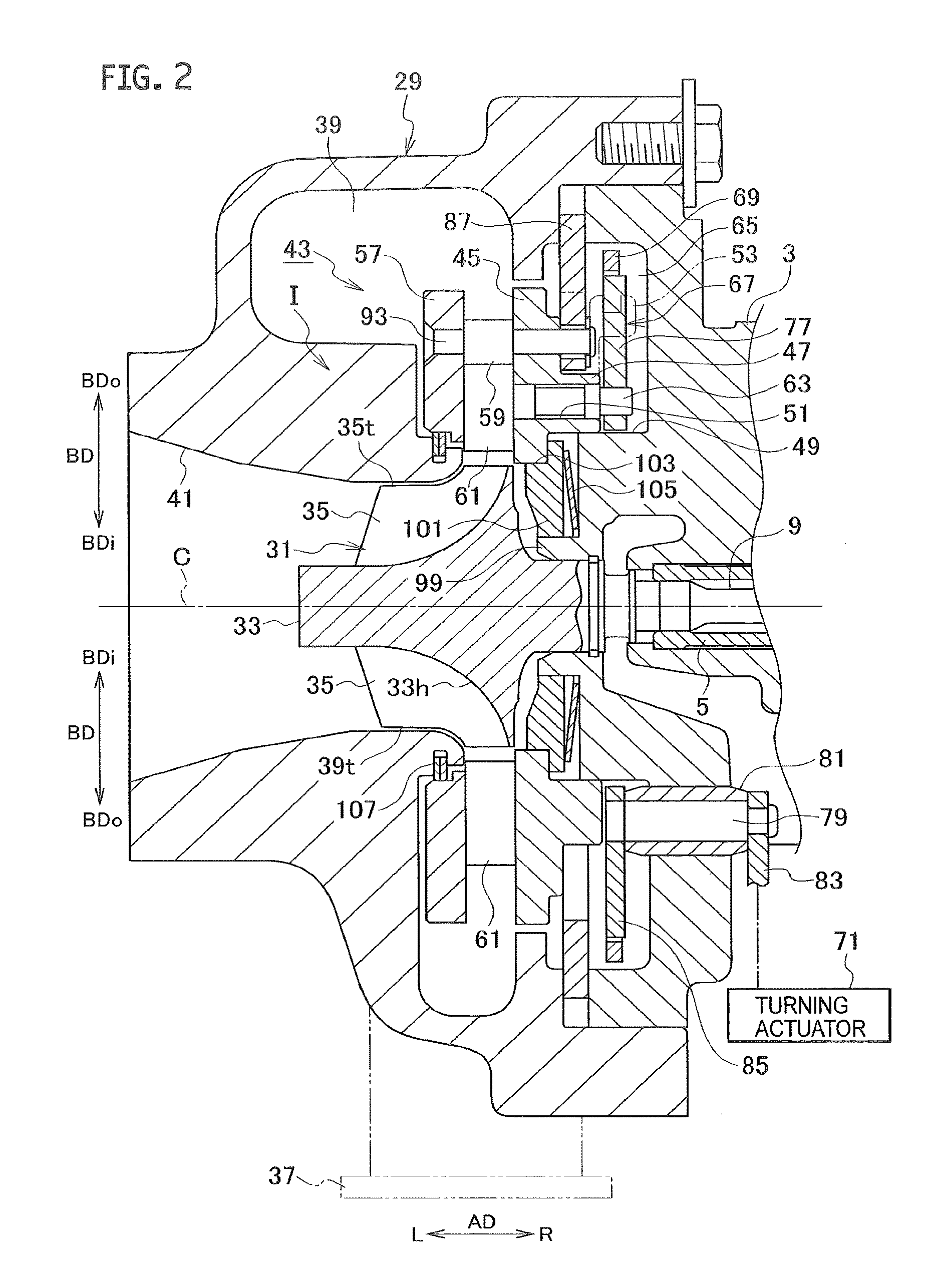
In a variable nozzle unit, at a position located away from and opposed to a first nozzle ring in a right-left direction, a second nozzle ring is provided integrally with the first nozzle ring through multiple connecting pins arranged in a circumferential direction. An inner edge portion of a support ring is connected to the first nozzle ring by riveting of one end portions of the multiple connecting pins. Each pin hole in the support ring is formed into such a shape extending in a radial direction of the support ring. A washer is provided between a rim of each pin hole in the support ring and a rivet head brought about by joining of the end portion of the corresponding connecting pin.

Description

CROSS REFERENCE TO RELATED APPLICATIONS[0001]This application is a continuation application of International Application No. PCT / JP2015 / 066579, filed on Jun. 9, 2015 which claims priority to Japanese Patent Application No. 2014-122123, filed on Jun. 13, 2014 the entire contents of which are incorporated by reference herein.BACKGROUND[0002]1. Technical Field[0003]The present disclosure relates to a variable nozzle unit and the like, which adjusts a passage area for (a flow rate of) an exhaust gas to be supplied to a turbine wheel side of a variable geometry turbocharger.[0004]2. Description of the Related Art[0005]In recent years, as described in Japanese Patent Application Publication No. 2009-243431 and Japanese Patent Application Publication No. 2009-243300, various developments have been made on a variable nozzle unit to be disposed inside a turbine housing of a variable geometry turbocharger. A specific configuration of a conventional variable nozzle unit is as described below.[...

Claims


Application Information

Patent Timeline
Patent Type & Authority Applications(United States)
IPC IPC(8): F02B37/22F02B37/24
CPCF02B37/24F02B37/22F01D17/165F05D2220/40F05D2250/14Y02T10/12
Inventor BAYOD, JOSE JAVIERITOU, KOUTAROUYOSHIZAKI, TAIKIINOUE, TOMOHIROBUNNO, KENJIASAKAWA, TAKAOSAKISAKA, RYOTATAKEUCHI, KAZUKO
Owner IHI CORP
Learn More