
Cable-Based Measuring System

a measuring system and cable technology, applied in the direction of mechanical measuring arrangement, instruments, using mechanical means, etc., can solve the problems of increasing the cost associated with packing an item, affecting the cost efficiency of operation of shipping vehicles filled with boxes that are 40% larger than the packaged items, and affecting the cost efficiency of operation

Active Publication Date: 2017-02-16
PACKSIZE LLC
View PDF14 Cites 1 Cited by
  • Summary
  • Abstract
  • Description
  • Claims
  • Application Information

AI Technical Summary

Benefits of technology

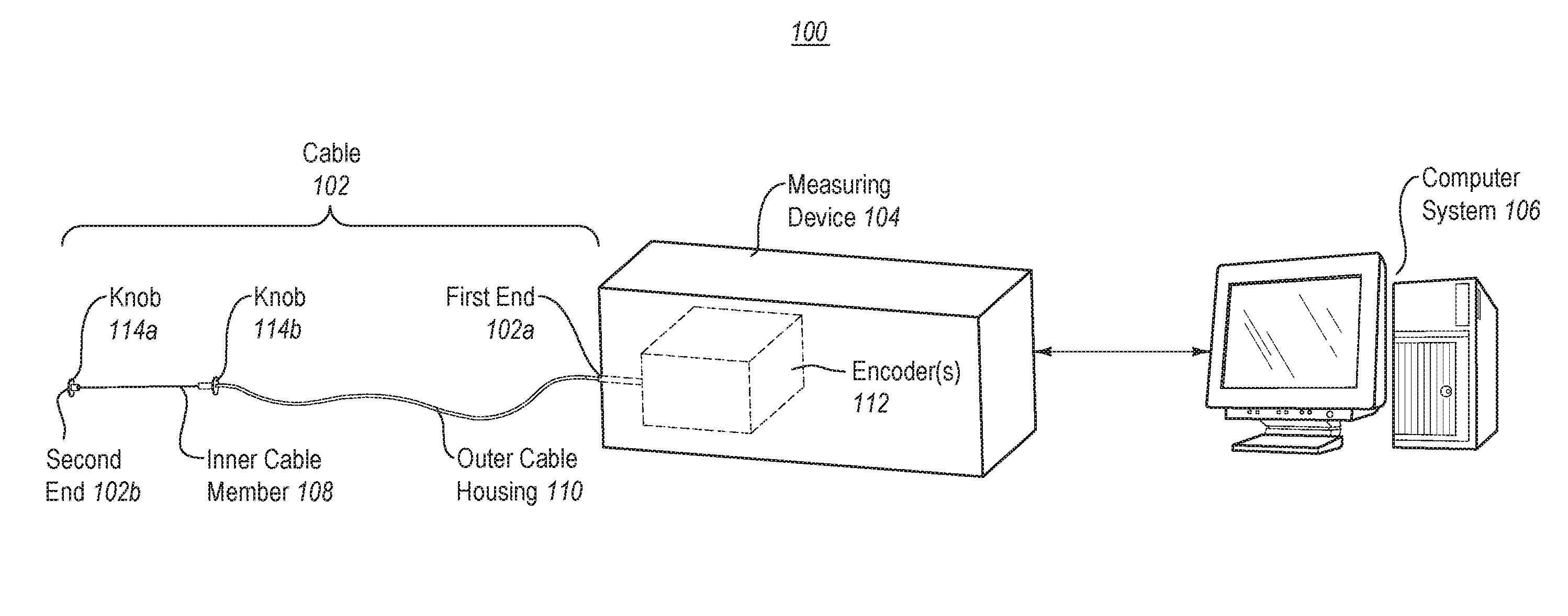
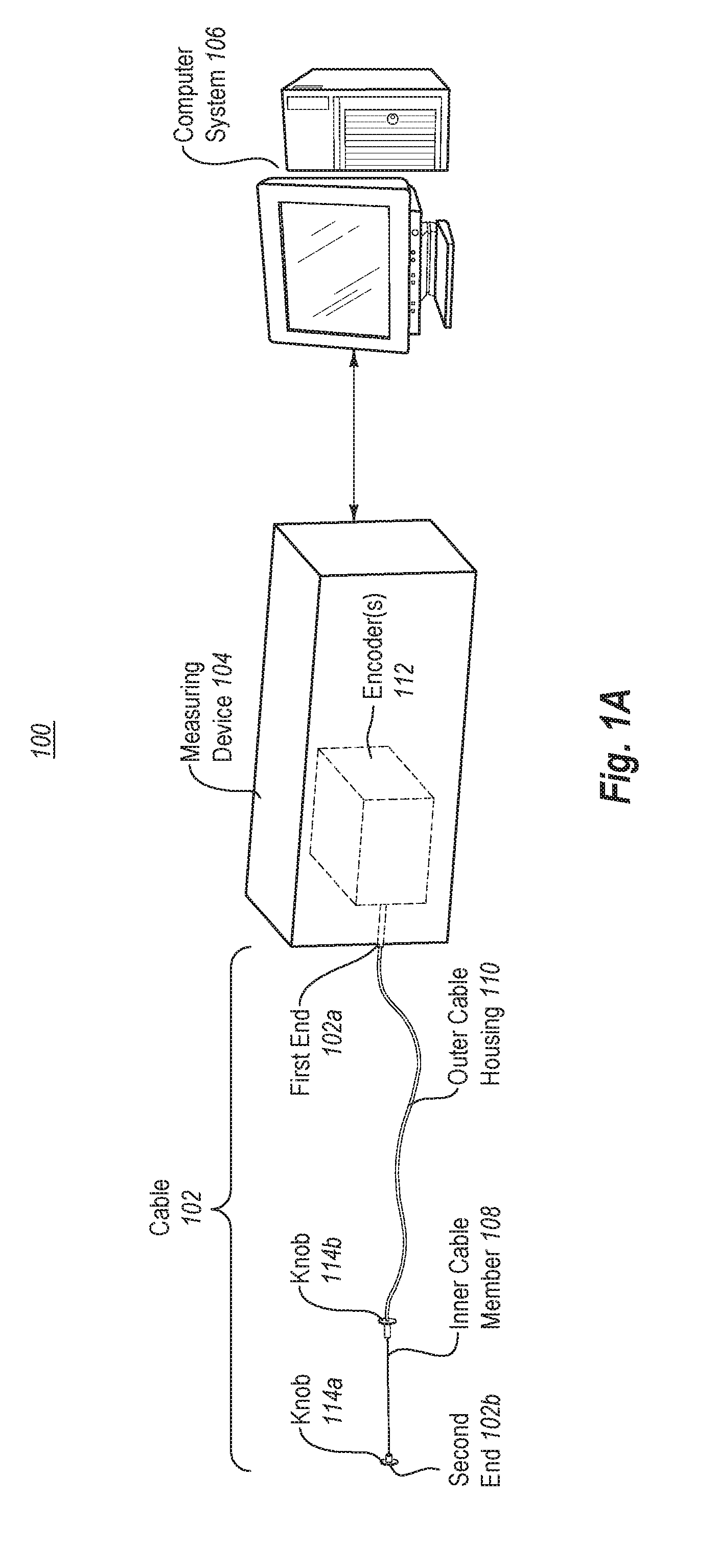
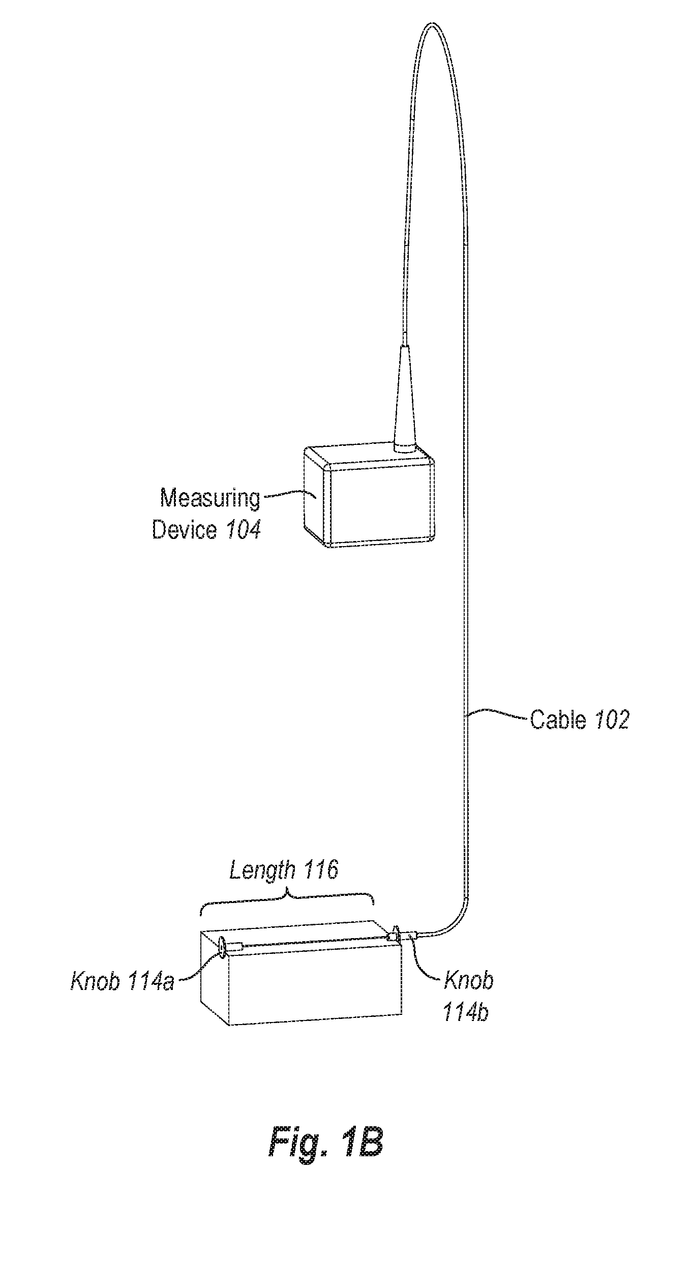
The present invention is a cable-based measuring system that can obtain measurements for an item to be packaged and communicate those measurements to material processing equipment for creation of an appropriately-sized box template. This system includes a cable with an inner cable member and an outer cable housing, and a measuring device with encoders that detect movement of the inner cable member and generate measurement information. The computer system initiates creation of a box template or updates an item database based on the measurement information. The measuring system can also identify the three-dimensional object measures and create or update a database entry for the object. The technical effects of this invention are improved precision and efficiency in creating box templates and updating item databases for packaging.

Problems solved by technology

Boxes that are too large for a particular item are more expensive than a box that is custom sized for the item due to the cost of the excess material used to make the larger box.
These filling materials further increase the cost associated with packing an item in an oversized box.
A shipping vehicle filled with boxes that are 40% larger than the packaged items is much less cost efficient to operate than a shipping vehicle filled with boxes that are custom sized to fit the packaged items.

Method used


Image

  • Cable-Based Measuring System
  • Cable-Based Measuring System
  • Cable-Based Measuring System

Examples


Embodiment Construction

[0024]The present invention extends to methods, systems, apparatus, and computer program products for a cable-based measuring system. The cable-based measuring system is a component of an on-demand material processing system that converts raw materials (e.g., fanfold materials) into physical box templates. As such, the cable-based measuring system can obtain measurements for an item to be packaged, and communicate those measurements to material processing equipment for creation of an appropriately-sized box template.

[0025]In some embodiments, a cable-based measuring system includes a cable. The cable comprises an inner cable member positioned within an outer cable housing. The inner cable member is configured to move linearly within the outer cable housing. The cable-based measuring system also includes a measuring device. The measuring device is configured to generate measurement information regarding movement of the inner cable member relative to the outer cable housing. A compute...


PUM

PropertyMeasurementUnit
dimensionsaaaaaaaaaa
sizesaaaaaaaaaa
sizeaaaaaaaaaa

Abstract

The present invention extends to methods, systems, apparatus, and computer program products related to a cable-based measuring system. The cable-based measuring system includes a cable, comprising an inner cable member configured to move linearly within an outer cable housing. The measuring system also includes a measuring device configured to generate measurement information regarding movement of the inner cable member relative to the outer cable housing using one or more encoders. A computer system receives the measurement information from the measuring device. The measurement information indicates length as a function of time, and represents three orthogonal dimensional measurements of a three-dimensional object. Based on the measurement information, the computer system identifies a length of each dimensional measurement, including a length, a width, and a height of the three-dimensional object. The computer system then initiates creation of a box template sized to accommodate the three-dimensional object and / or updates a database.

Description

[0001]This application is a divisional of U.S. patent application Ser. No. 14 / 370,741, filed Jul. 3, 2014, and entitled “CABLE-BASED MEASURING SYSTEM”, which claims priority to and the benefit of PCT Application No. PCT / US2012 / 070659, filed Dec. 19, 2012, and entitled “CABLE-BASED MEASURING SYSTEM”, which claims the benefit of and priority to the following applications: U.S. Provisional Application No. 61 / 587,013, filed Jan. 16, 2012, and entitled “CABLE-BASED MEASURING SYSTEM” and U.S. Provisional Application No. 61 / 584,588, filed Jan. 9, 2012, and entitled “CABLE-BASED MEASURING SYSTEM”. All the aforementioned applications are incorporated by reference herein in their entirety.BACKGROUND1. Background and Relevant Art[0002]Computer systems and related technology affect many aspects of society. Indeed, the computer system's ability to process information has transformed the way we live and work. Computer systems now commonly perform a host of tasks (e.g., word processing, scheduling...

Claims


Application Information

Patent Timeline
Patent Type & Authority Applications(United States)
IPC IPC(8): G01B11/04B65B57/12G01D5/02G01B3/11G01D5/26
CPCG01B11/043G01B3/11B65B57/12G01D5/02G01D5/26G01B7/02B65B2210/04G01B21/02G01B5/0021G01B5/02G01B2210/58
Inventor PETTERSSON, NIKLAS
Owner PACKSIZE LLC
Learn More