Bipolar lightning protection apparatus having light emitting unit

Active Publication Date: 2017-02-16
CHUNG YOUNG KI
View PDF4 Cites 6 Cited by
  • Summary
  • Abstract
  • Description
  • Claims
  • Application Information

AI Technical Summary

Benefits of technology

The present invention provides a bipolar lightning protection apparatus with a light emitting unit that can confirm whether or not the apparatus operates from outside by receiving power applied from lightning current. The apparatus includes a light emitting unit connection block that protects the light emitting element and fastening bolt, a diffusion lens for tightly sealing to prevent penetration of foreign materials and diffusing the radiated light, and a blinking position that improves light distribution and brightness. The technical effects of this invention include giving a psychological sense of safety to the user, ensuring a normal operation of safely flowing impulse current of lightning to the earth, and improving the overall appearance of the apparatus.

Problems solved by technology

However, although the lightning protection apparatus according to the prior art performs a normal operation of safely flowing impulse current of lightning generated by a thundercloud to the earth, a user may not know clearly whether or not the lightning protection apparatus normally operates.
Accordingly, although a thundercloud approaches in the daytime when the surrounding areas are bright, this cannot be confirmed at all.
Particularly, since there is no way to confirm a grounding fault although grounding of the rod to the earth is poor, this can be misunderstood as a normal operation, and thus a fire or damage to a building or loss of lives may occur due to the lightning.
Furthermore, since the lightning protection apparatus is a structure installed at the uppermost part of a building and a worker himself or herself should go up to a narrow work space to inspect operation of the lightning protection apparatus, the work is dangerous and requires an excessive large amount of time.

Method used


Image

  • Bipolar lightning protection apparatus having light emitting unit
  • Bipolar lightning protection apparatus having light emitting unit
  • Bipolar lightning protection apparatus having light emitting unit

Examples


Embodiment Construction

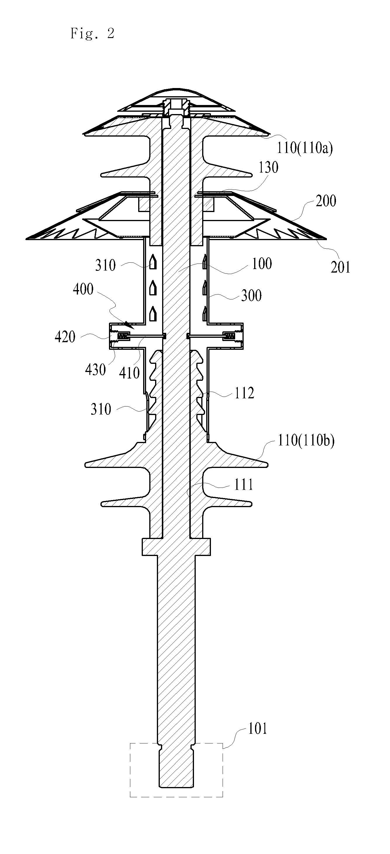
[0046]A preferred embodiment of the present invention will be hereafter described in detail, with reference to FIGS. 2 to 8.

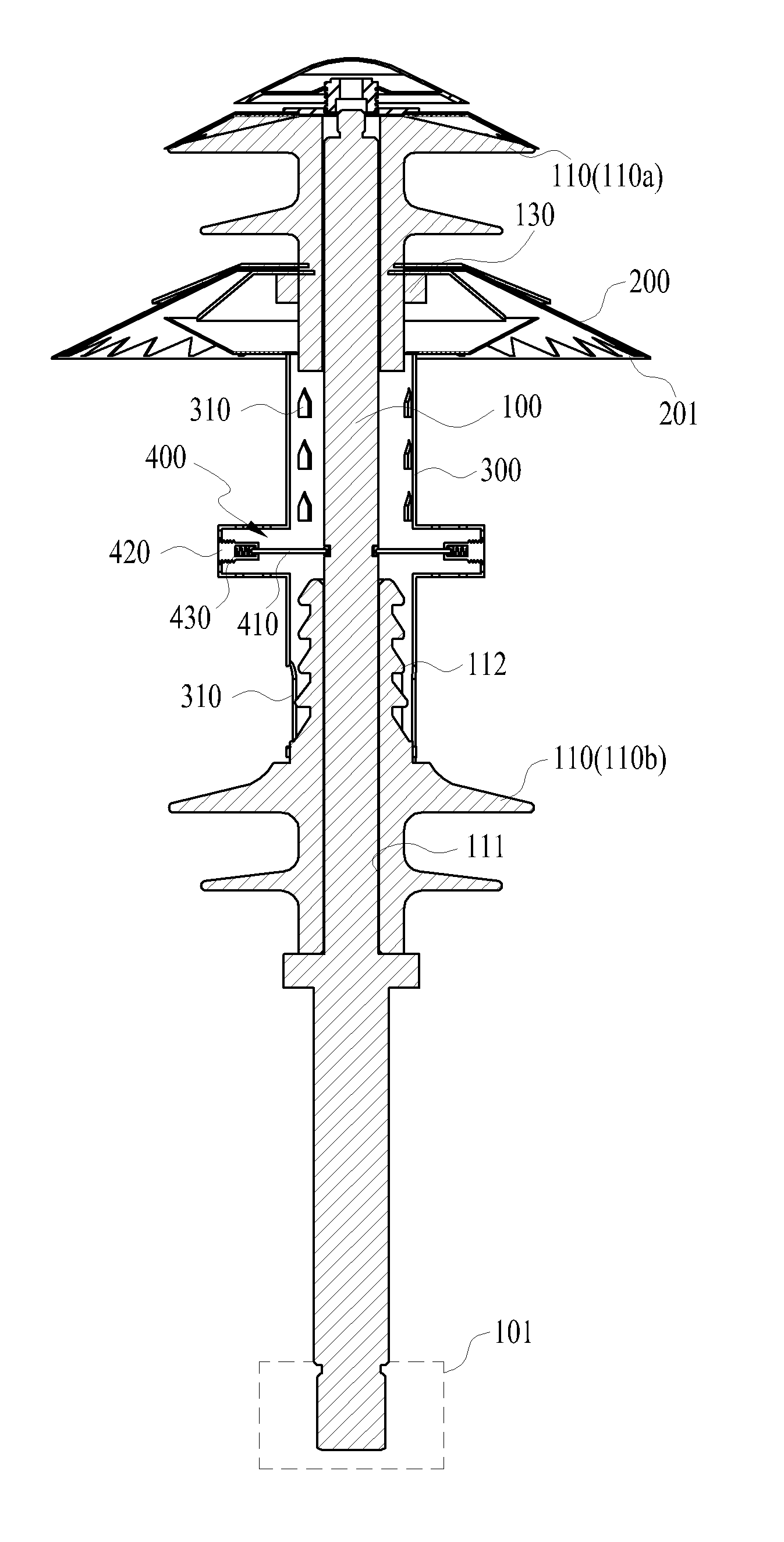
[0047]A bipolar lightning protection apparatus having a light emitting unit according to present invention is configured to include a rod member 100 charged with ground charges, a charging plate 200 or a charging tube 300 charged by a thundercloud, and a light emitting unit 400 electrically connected between the rod member 100 and the charging plate 200 or the charging tube 300 and emitting light by electrical energy charged in the charging plate 200 or the charging tube 300 by the thundercloud.

[0048]First, the rod member 100 is extended at a predetermined length to be vertically erected on the outdoor ground surface and performs a function of charging the ground charges.

[0049]In addition, a fixing plate 101 capable of stably fixing the rod member 100 and further improving an area contacting with the earth can be additionally installed at the lower end of the r...


PUM


Abstract

The present invention relates to a bipolar lightning protection apparatus having a light emitting unit, and in the bipolar lightning protection apparatus configured of a rod member charged with ground charges and a charging plate or a charging tube charged by a thundercloud, the bipolar lightning protection apparatus includes a light emitting unit electrically connected between the rod member and the charging plate or the charging tube and emitting light by electrical energy charged in the charging plate or the charging tube by the thundercloud.Accordingly, a psychological sense of safety can be given to a user by allowing the user to clearly confirm with naked eyes that a normal operation of safely flowing impulse current of lightning to the earth is performed.

Description

BACKGROUND OF THE INVENTION[0001]Field of the Invention[0002]The present invention relates to a bipolar lightning protection apparatus having a light emitting unit, and more specifically, to a bipolar lightning protection apparatus having a light emitting unit, which can easily confirm whether or not the lightning protection apparatus operates from outside by receiving power applied from lightning current of lightning and radiating light.[0003]Background of the Related Art[0004]Generally, a lightning protection apparatus is installed at the uppermost part of a building to safely discharge the charges accumulated in a thundercloud to the earth by forming a discharge path between the thundercloud and the earth.[0005]When the thundercloud approaches the earth, the potential difference between the thundercloud and the earth reaches one hundred million volts (V).[0006]However, although a dielectric breakdown, i.e., lightning, does not occur between the earth and the thundercloud since th...

Claims


Application Information

Patent Timeline
IPC IPC(8): F21V33/00G08B7/06G08B5/36H02G13/00F21V17/12
CPCF21V33/0076H02G13/80H02G13/40F21Y2101/02G08B5/36G08B7/06F21V17/12H02G13/00
Inventor CHUNG, YOUNG-KILEE, KANG SOO
Owner CHUNG YOUNG KI
Why Eureka
Try Eureka