
Security threads and stripes

Active Publication Date: 2017-02-16
SICPA HLDG SA
View PDF9 Cites 5 Cited by
  • Summary
  • Abstract
  • Description
  • Claims
  • Application Information

AI Technical Summary

Benefits of technology

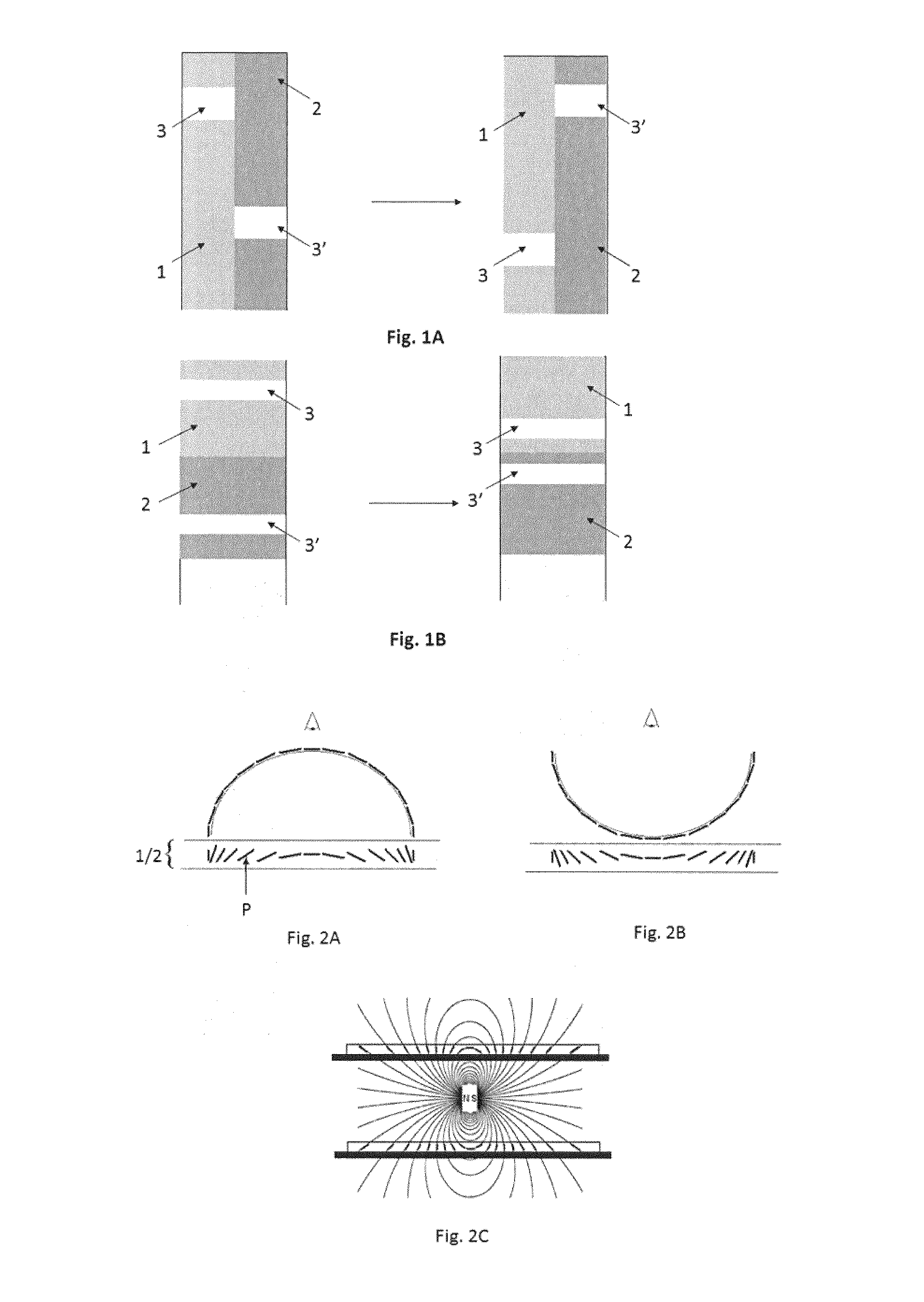
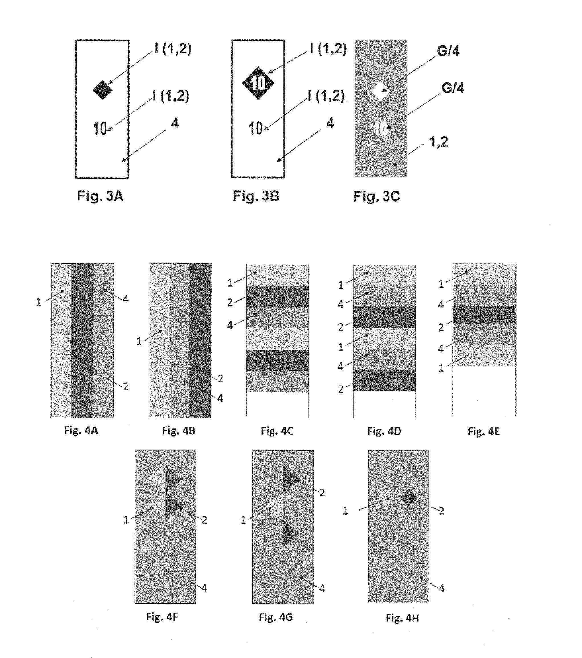
The present invention provides a new type of security thread or stripe which has improved resistance to counterfeiting and is easier to produce. The thread or stripe comprises a first hardened coating containing non-spherical magnetic or magnetizable pigment particles oriented in a convex curvature, a second hardened coating containing similar particles oriented in a concave curvature, and a holographic metallic layer. The first and second hardened coatings are at least partially jointly visible from one side of the thread or stripe, creating a plural rolling bar effect. The combination of these layers results in a more visually appealing and secure product. The invention also provides simpler and more efficient processes for producing the security threads and stribes.

Problems solved by technology

Such images are known to be easily recognized by the man on the street and the illusive aspect cannot be reproduced by commonly available office equipment for color scanning, printing and copying.
However, disclosed methods to obtain a security element comprising a substrate and combining at least two areas, one area comprising magnetic or magnetizable pigment particles oriented so as to follow a negative curvature and another area comprising magnetic or magnetizable oriented to follow a positive curvature require a step of applying a magnetic-field generating device from above the substrate, i.e. the device faces the not yet hardened composition comprising the magnetic or magnetizable pigment particles, therefore increasing the complexity of the overall manufacturing process of the security element.
Such a combination enhances the resistance upon circulation and time of the security thread or stripe and enhances the security and visibility of said security thread or stripe and thus increases the difficulty of the counterfeiting.

Method used


Image

  • Security threads and stripes
  • Security threads and stripes
  • Security threads and stripes

Examples


Embodiment Construction

[0023]The following definitions are to be used to interpret the meaning of the terms discussed in the description and recited in the claims.

[0024]As used herein, the article “a” indicates one as well as more than one and does not necessarily limit its referent noun to the singular.

[0025]As used herein, the term “about” in conjunction with an amount or value means that the amount or value in question may be the specific value designated or some other value in its neighborhood. Generally, the term “about” denoting a certain value is intended to denote a range within ±5% of the value. As one example, the phrase “about 100” denotes a range of 100 ±5, i.e. the range from 95 to 105. Preferably, the range denoted by the term “about” denotes a range within 3% of the value, more preferably ±1%. Generally, when the term “about” is used, it can be expected that similar results or effects according to the invention can be obtained within a range of ±5% of the indicated value.

[0026]As used herei...


PUM

PropertyMeasurementUnit
Coloraaaaaaaaaa
Transparencyaaaaaaaaaa
Magnetismaaaaaaaaaa

Abstract

The present invention relates to the field of the protection of value documents and value commercial goods against counterfeit and illegal reproduction. In particular, the present invention relates to security threads or stripes comprising a holographic metallic layer; a first transparent substrate; a second transparent substrate; a first hardened coating and a second hardened coating, wherein a first plurality of non-spherical magnetic or magnetizable pigment particles of the first hardened coating are oriented so as to follow a convex curvature and wherein the second plurality of non-spherical magnetic or magnetizable pigment particles of the second hardened coating are oriented so as to follow a concave curvature so as to form a plural rolling bar effect.

Description

FIELD OF THE INVENTION[0001]The present invention relates to the field of the protection of value documents and value commercial goods against counterfeit and illegal reproduction. In particular, the present invention relates to security threads or stripes to be incorporated into or onto security documents, said security threads or stripes exhibiting highly dynamic visual motion effect upon tilting.BACKGROUND OF THE INVENTION[0002]With the constantly improving quality of color photocopies and printings and in an attempt to protect security documents such as banknotes, value documents or cards, transportation tickets or cards, tax banderols, and product labels against counterfeiting, falsifying or illegal reproduction, it has been the conventional practice to incorporate various security means in these documents. Typical examples of security means include security threads or stripes, windows, fibers, planchettes, foils, decals, holograms, watermarks, security inks comprising opticall...

Claims


Application Information

Patent Timeline
IPC IPC(8): B42D25/355B42D25/45B32B5/16B42D25/378B42D25/364B42D25/373B42D25/328B42D25/369
CPCB42D25/355B42D25/328B42D25/45B42D25/369B42D25/378B32B2307/412B42D25/373B32B5/16B32B2255/00B32B2307/208B42D25/364B05D3/207B05D7/53B32B27/08B32B27/304B32B27/32B32B27/34B32B27/36B32B2250/03B32B2250/24B32B2255/10B32B2255/20B32B2255/205B32B2255/26B32B2270/00B32B2307/40B32B2307/402B32B2425/00B32B2554/00B32B5/00B42D25/351
Inventor RITTER, GEBHARD
Owner SICPA HLDG SA
Learn More