
Conductive bridging method, bridging structure, touch panel and touch control display apparatus

a bridging structure and conductive technology, applied in the direction of instruments, computing, electric digital data processing, etc., can solve the problems of reduced yield, increased process complexity, and inability to enable the y-direction electrode and the x-direction electrode to communicate, so as to reduce the process cost, and improve the effect of bridging stability

Active Publication Date: 2017-02-09
BOE TECH GRP CO LTD +1
View PDF6 Cites 2 Cited by
  • Summary
  • Abstract
  • Description
  • Claims
  • Application Information

AI Technical Summary

Benefits of technology

The present invention provides a method for forming a conductive connection by using a conductive dispersion liquid that automatically repels a region of a self-assembled monolayer but stays in a bridging region without the self-assembled monolayer. This method simplifies the process, improves pattern quality, reduces process cost, and enhances optical transmittance of the touch module. Additionally, this method facilitates a large-area manufacturing process for a touch screen.

Problems solved by technology

With regard to a bridging process for receivers (Rx) and transmitters (Tx) of a touch screen, a bridging electrode needs to connect two X-direction electrodes located at two sides of a Y-direction electrode, and can not enable the Y-direction electrode and the X-direction electrode to communicate.
In a traditional metal bridging process, the process complexity is increased due to processes such as evaporation coating, photoresist-applying, developing and etching of a metal target material.
Moreover, in an etching process, the metal electrode is likely to be etched because the alignment is not precise enough, or the metal electrode may be broken, thereby causing a reduction in yield.
Although the ink-jet printing is a good way for patterning, in view of industrialized mass production, problems such as a size of the ink head, a dribbling amount and the operation continuity for ink-jet printing have always been a bottleneck required to be solved.
Particularly, once a liquid drop deviates or displaces, Rx and Tx may be likely to be connected together due to a spreading problem and a film-forming uncertainty after the liquid drop dribbles.
In the prior art, a silk-screen printing machine is also used to realize patterning for the electrode material, but it is found in actual processing that, the silk-screen printing machine is high in input cost, and high in pattern typesetting cost.
In addition, the precision of a silk screen also affects the resolution.

Method used


Image

  • Conductive bridging method, bridging structure, touch panel and touch control display apparatus
  • Conductive bridging method, bridging structure, touch panel and touch control display apparatus
  • Conductive bridging method, bridging structure, touch panel and touch control display apparatus

Examples


Embodiment Construction

[0060]The detailed description of the present invention will be further explained below in detail in connection with drawings and embodiments. The following embodiments are intended to illustrate the present invention, but not to limit a scope thereof.

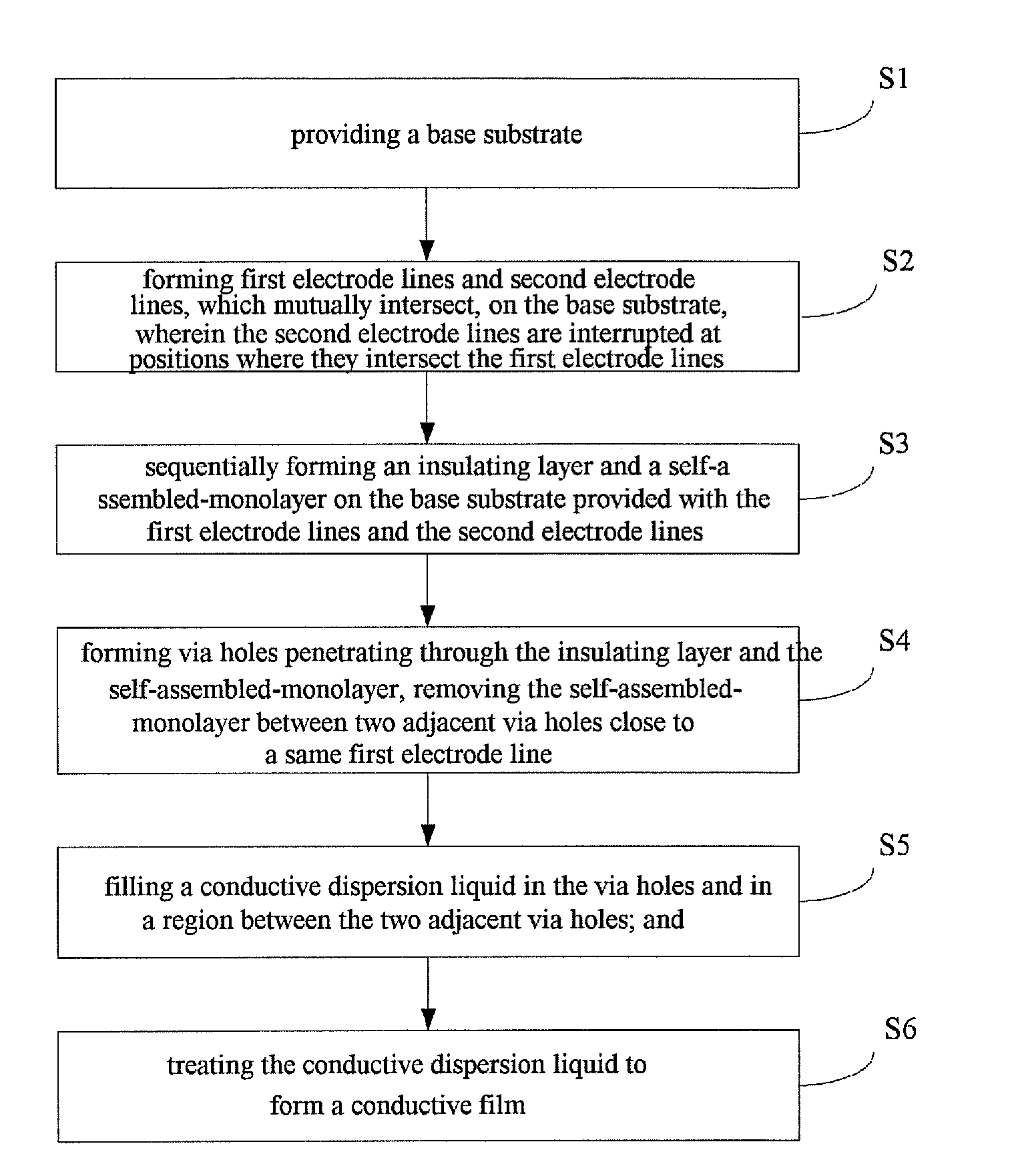
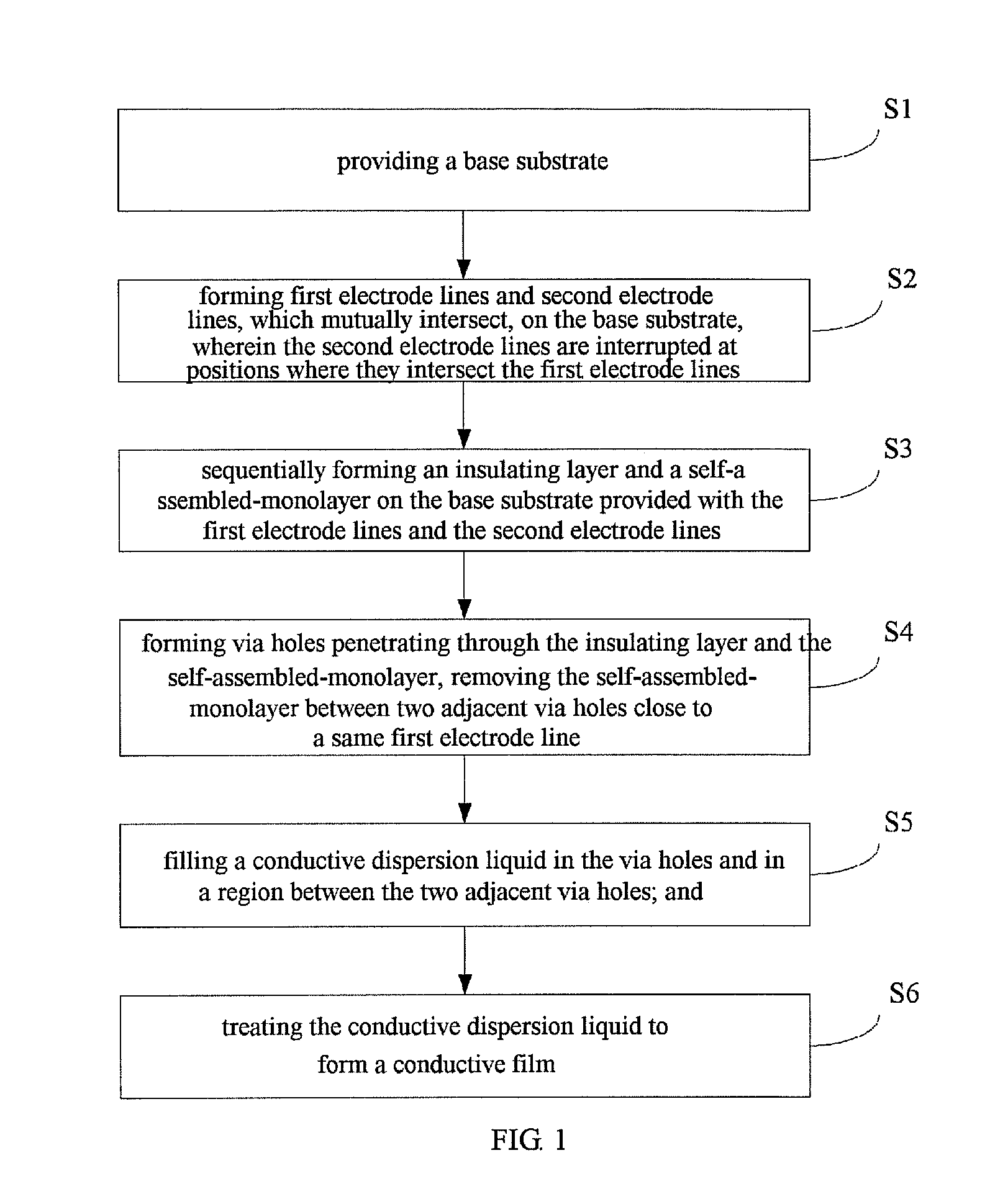
[0061]As shown in FIG. 1, the present invention provides a conductive bridging method, specifically comprising:

[0062]step 1, providing a base substrate 1;

[0063]step 2, forming first electrode lines 3 and second electrode lines 2, which mutually intersect, on the base substrate 1, wherein the second electrode lines 2 are interrupted at positions where they intersect the first electrode lines 3;

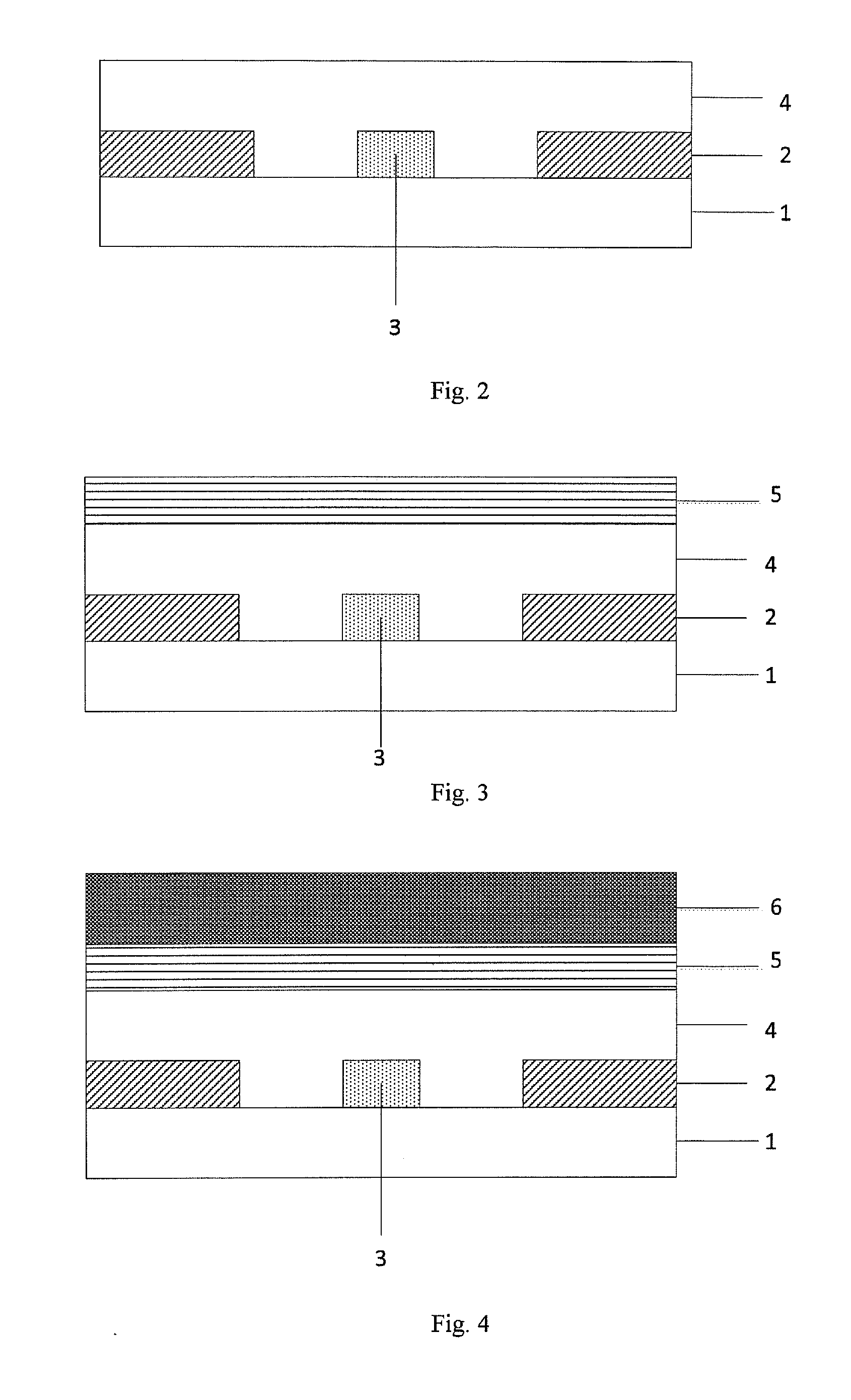
[0064]step 3, sequentially forming an insulating layer 4 and a self-assembled-monolayer 5 on the base substrate provided with the first electrode lines 3 and the second electrode lines 2;

[0065]step 4, forming via holes 9 penetrating through the insulating layer 4 and the self-assembled-monolayer 5, removing the self-assembled-monolayer 5 between t...


PUM


Abstract

The present invention relates to the technical field of display by a touch screen, and particularly relates to a conductive bridging method, a bridging structure, a touch panel and a touch control display apparatus. The conductive bridging method comprises: sequentially forming an insulating layer and a self-assembled-monolayer on the base substrate provided with first electrode lines and second electrode lines which mutually intersect; forming via holes penetrating through the insulating layer and the self-assembled-monolayer; removing the self-assembled-monolayer between two adjacent via holes close to a same first electrode line; and forming a conductive film in the via holes and in a region between two adjacent via holes. In this way, a bridging connection is achieved with the help of the electrical conductivity of the conductive film.

Description

RELATED APPLICATIONS[0001]This application claims the priority to Chinese Patent Application No. 201510138235.1, filed on Mar. 26, 2015, which is incorporated herein by reference.TECHNICAL FIELD[0002]The present invention relates to the technical field of display by a touch screen, and particularly relates to a conductive bridging method, a bridging structure, a touch panel and a touch control display apparatus.BACKGROUND ART[0003]As a dependence of people on a mobile product has increased, touch screen technologies, including an original resistive touch screen, as well as newest outboard full-fit touch screen, on-cell (a touch sensor is assembled on a liquid crystal panel), HIC, full in cell (a touch sensor is embedded inside a display screen), and the like, have advanced rapidly. In these touch screen technologies, a self-capacitance type capacitive touch screen and a mutual-capacitance type capacitive touch screen are most widely used. In a traditional touch screen technology, th...

Claims


Application Information

Patent Timeline
Patent Type & Authority Applications(United States)
IPC IPC(8): G06F3/044G06F3/041
CPCG06F3/0412G06F3/044G06F3/041G06F2203/04103G06F2203/04111G06F3/0446G06F3/0443
Inventor FENG, XIANGWEI, XIANGDONGLIU, JINGQIU, YUN
Owner BOE TECH GRP CO LTD
Learn More