
Method and device for spreading fiber strands

Inactive Publication Date: 2017-02-09
C CRAMER WEBEREI HEEK NIENBORG
View PDF9 Cites 6 Cited by
  • Summary
  • Abstract
  • Description
  • Claims
  • Application Information

AI Technical Summary

Benefits of technology

The present invention provides a low-cost method for spreading fibers, which can be used on fibers of different characters, without changing their composition. The method involves processing fiber strands when they are dry, without requiring energy for dewatering, heating or drying. The method allows for a consistent and wider final width of the fiber strand, with a lesser final thickness, resulting in a lightweight composite with good mechanical properties. The method also allows for a more consistent process result, resulting in a more desirable final width of the spread fiber strand.

Problems solved by technology

This kind of spreading method is energy-intensive and can only be used on fiber strands that are electrically conductive and can thus be electrically charged.
This release agent adheres to the fibers and in this blown method, impedes a uniform spreading of the fiber strand.
Moreover, a removal of the release agent is difficult, since firstly, release agents with different properties are used, and secondly, these release agents prevent the damaging [sic], e.g. of fragile carbon fibers during subsequent processing.
A method of this kind is very difficult to control and results in irregular final widths of the fiber strand.
But the disadvantage of this method is that the release agent surrounding the filaments changes in the water bath.
Depending on the nature of the release agent, this can also result in a chemical change.
But in every case, the quantity ratio of fiber to release agent in the fiber strand is affected, which is undesirable.
Another disadvantage of the method consists in that the spread fiber strip emerging from the water has to be dewatered and dried.
This drying process is energy-intensive, so that a mechanical dewatering step has to be provided before the drying.
In this method as well, the fiber strand is heated before, during and after the spreading by the use of a heating apparatus in order to break up thermally or chemically the release agent present on the fibers, which firstly affects the release agent, and secondly is associated with energy costs.
A change to the release agent, however, is undesirable, since the release agent in the fiber strand is needed for subsequent processing steps.

Method used


Image

  • Method and device for spreading fiber strands
  • Method and device for spreading fiber strands
  • Method and device for spreading fiber strands

Examples


Embodiment Construction

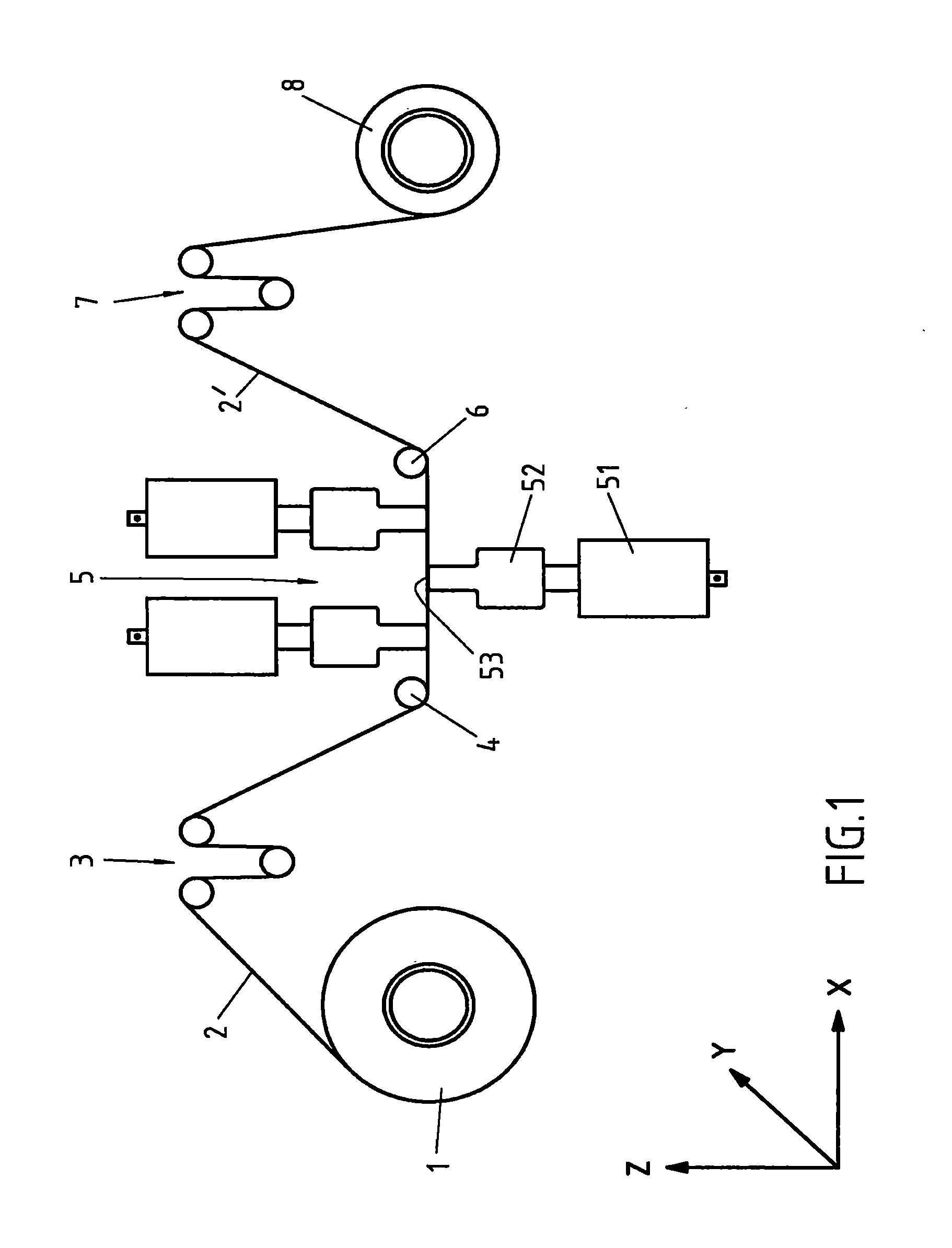
[0026]The invention is not restricted to these exemplary embodiments. The basic sketch in FIG. 1 depicts the fundamental passage of a fiber strand 2 to be spread, through the spreader station 5, proceeding from the unwinding unit 1, out to the winding unit 8. The fiber strand 2 in this case pertains to a 12K fiber strand, that is, the fiber strand consists of 12,000 filaments, which are arranged continuously in the fiber strands 2, side by side, and each one surrounded by a release agent. This release agent prevents the fiber strand 2 from being damaged during its movement. The employed fiber strand 2 is delivered on a spool of the unwinding unit 1 and is unwound from this spool. Due to the unwinding of the fiber strand 2 from the spool, different unwinding positions would result with each revolution. In order that this fiber strand 2 is always supplied to the same position of the following dancing roller 3, which conducts it to the spreader station 5, so that the fiber strand 2 is ...


PUM

PropertyMeasurementUnit
Speedaaaaaaaaaa
Frequencyaaaaaaaaaa
Frequencyaaaaaaaaaa

Abstract

A method and a device for spreading a fiber strand to provide a strip-type fiber strand. In particular, the initial fiber strand is provided with an initial width and thickness, and is then spread to form the strip-type fiber strand having a greater final width and a smaller final thickness as compared to the initial width and thickness. The fiber strand consists of continuous multifilament fibers.

Description

CROSS-REFERENCE TO RELATED APPLICATIONS[0001]This application is a national phase application pursuant to 35 U.S.C. 371 of International Application No. PCT / EP2015 / 055689, filed Mar. 18, 2015, which claims priority to German Application No. 10 2014 105 464.4, filed Apr. 16, 2014. These applications are hereby incorporated by reference in their entireties.FIELD OF THE INVENTION[0002]The invention relates to a method and a device for spreading of a fiber strand, which features an initial width and an initial thickness, to a strip-type fiber strand with greater final width and with smaller final thickness, wherein the fiber strand consists of continuous multifilament fibers.BACKGROUND OF THE INVENTION[0003]The spreading of fiber strands has long been known and is employed on fiber strands made of polymer fibers to improve physical properties, since due to the spreading, twisting of the filaments in the fiber strand, for example, can be eliminated and a fiber strand with filaments posit...

Claims


Application Information

Patent Timeline
IPC IPC(8): D02J1/18
CPCD02J1/18
Inventor KEPPEL, JURGENRAKOVAC, ANDYHOLTMANN, THOMAS
Owner C CRAMER WEBEREI HEEK NIENBORG
Learn More