
Expandable vertebral implant

a technology of expanding vertebrae and spacers, which is applied in the field of expanding vertebrae, can solve the problems of affecting the ability of bone and bone structures to provide support and structure, and the ability of bone and bone structures to be susceptible, so as to maintain the separation of bone and bone of the joint, and increase the height of the spacer

Active Publication Date: 2017-02-09
GLOBUS MEDICAL INC
View PDF5 Cites 4 Cited by
  • Summary
  • Abstract
  • Description
  • Claims
  • Application Information

AI Technical Summary

Benefits of technology

The spacer effectively stabilizes adjacent vertebrae by providing adjustable support, reducing tissue trauma during insertion, and allowing for optimal separation and distribution of forces, promoting vertebral endplate preservation and bone ingrowth for long-term stability.

Problems solved by technology

Bones and bony structures are susceptible to a variety of weaknesses that can affect their ability to provide support and structure.

Method used


Image

  • Expandable vertebral implant
  • Expandable vertebral implant
  • Expandable vertebral implant

Examples


Embodiment Construction

[0070]As required, detailed embodiments are disclosed herein; however, it is to be understood that the disclosed embodiments are merely examples and that the systems and methods described below can be embodied in various forms. Therefore, specific structural and functional details disclosed herein are not to be interpreted as limiting, but merely as a basis for the claims and as a representative basis for teaching one skilled in the art to variously employ the present subject matter in virtually any appropriately detailed structure and function. Further, the terms and phrases used herein are not intended to be limiting, but rather, to provide an understandable description of the concepts.

[0071]The terms “a” or “an”, as used herein, are defined as one or more than one. The term plurality, as used herein, is defined as two or more than two. The term another, as used herein, is defined as at least a second or more. The terms “including” and “having,” as used herein, are defined as comp...


PUM


Abstract

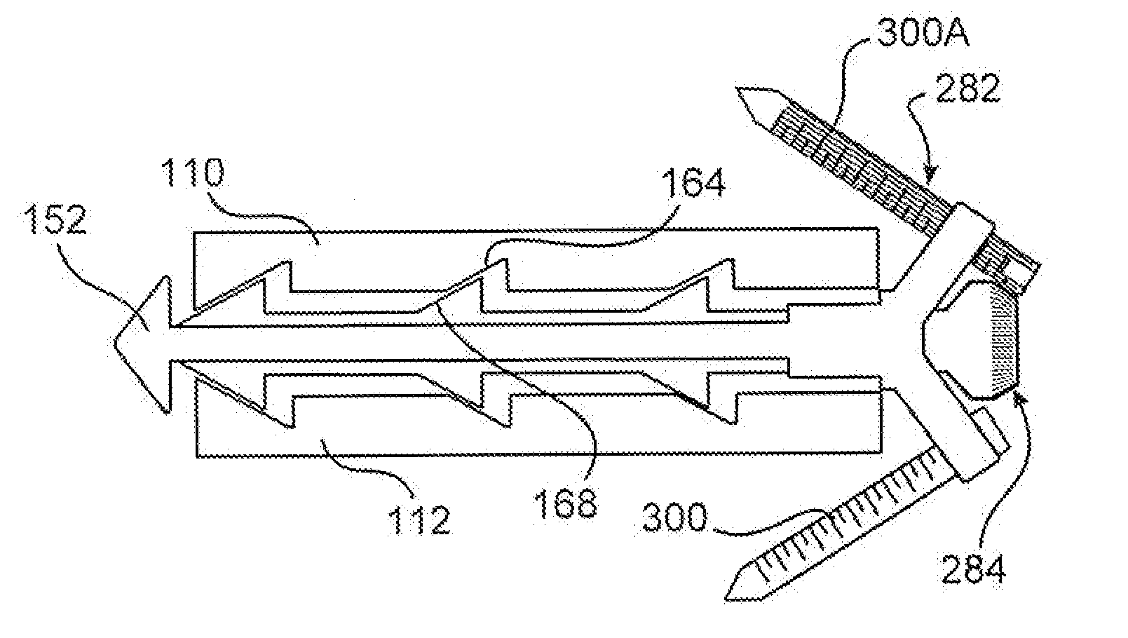
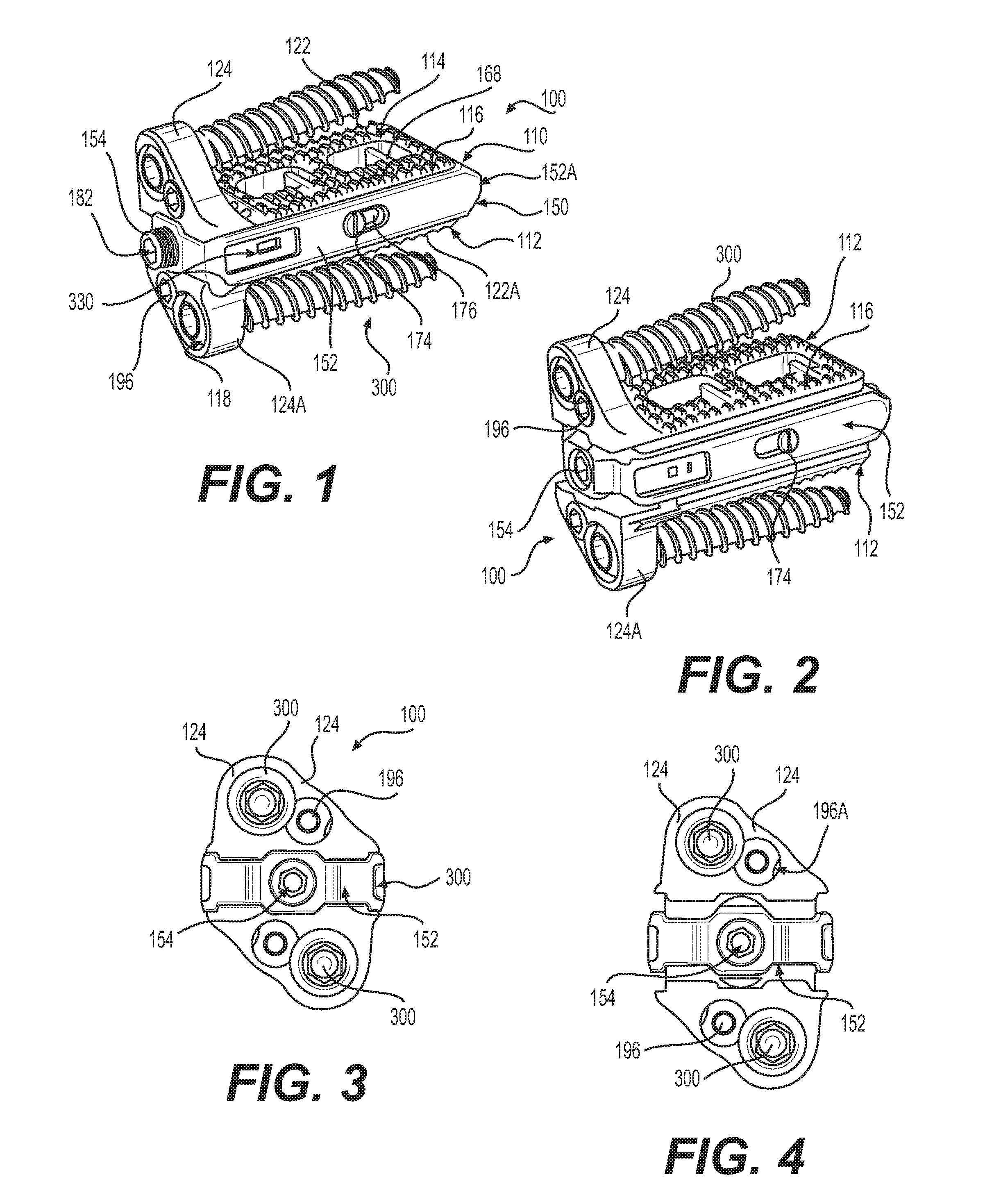
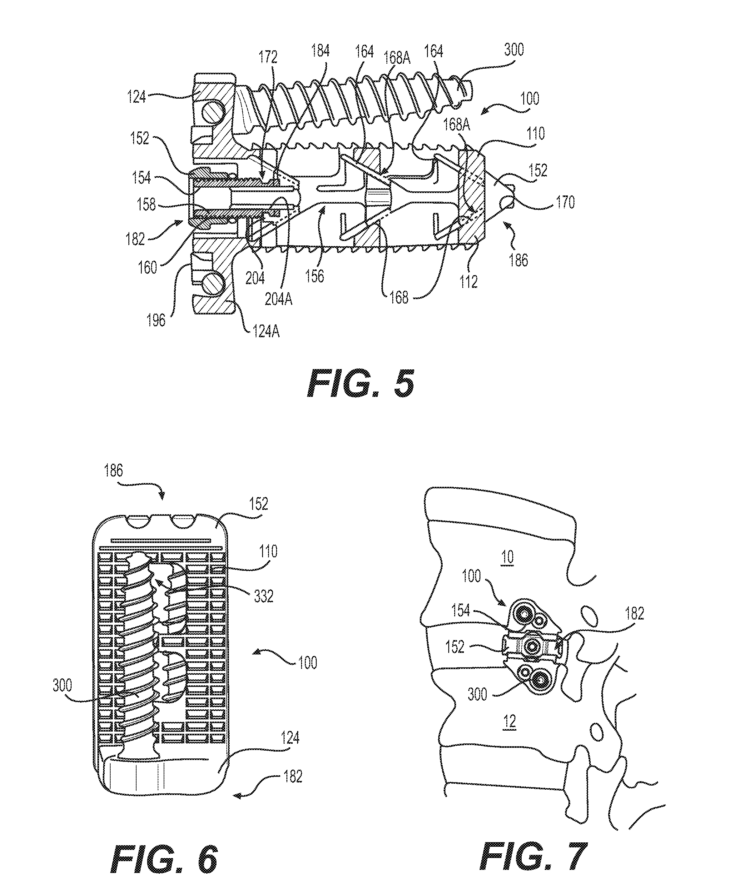
A joint spacer therapeutically maintains separation of bones of a joint. A carriage is slideably retained within the frame and has at least one ramped surface. An actuator screw is threadably engaged with the frame, and rotatably connected to the carriage, to cause the carriage to slideably move within the frame when the actuator screw is rotated. First and second endplates engage the bones of the joint, and each has at least one ramped surface that is mateable with the ramped surface of the carriage, whereby when the carriage is slideably moved by rotation of the actuator screw, the endplates ramped surface slides against the carriage ramped surface to cause the endplates to move along an axis transverse to the longitudinal axis of the frame, to increase the height of the spacer. Piercing elements are connected to the carriage to pierce bone of the joint when the carriage is moved.

Description

CROSS REFERENCE TO RELATED APPLICATIONS[0001]This application is a continuation application of U.S. patent application Ser. No. 13 / 711,204, filed Dec. 11, 2012. This application is also a continuation-in part of U.S. patent application Ser. No. 14 / 940,322, filed on Nov. 13, 2015, which is a continuation of U.S. patent application Ser. No. 13 / 845,645, filed on Apr. 3, 2013, now U.S. Pat. No. 9,216,095, which is a continuation-in-part of U.S. patent application Ser. No. 13 / 451,230, filed on Apr. 19, 2012, now U.S. Pat. No. 8,518,120, which is a continuation-in-part of U.S. patent application Ser. No. 13 / 440,158, filed on Apr. 5, 2012, now U.S. Pat. No. 8,679,183, which is a continuation-in-part of U.S. patent application Ser. No. 13 / 273,994, filed on Oct. 14, 2011, now U.S. Pat. No. 9,358,126, which is a continuation-in-part of U.S. patent application Ser. No. 12 / 823,736, filed on Jun. 25, 2010, now U.S. Pat. No. 8,685,098, which is a continuation of U.S. patent application Ser. No. 1...

Claims


Application Information

Patent Timeline
Patent Type & Authority Applications(United States)
IPC IPC(8): A61F2/44
CPCA61F2/4455A61F2002/30433A61F2002/30579A61F2002/30578A61F2002/30556A61B17/8033A61F2/4425A61F2002/30387A61F2002/30471A61F2002/305A61F2002/30507A61F2002/30523A61F2002/30904A61F2002/4635A61F2/447
Inventor IOTT, ANDREWADAMS, MARKGLERUM, CHADSEIFERT, JODY L.BECHTEL, MATTHEWGAHMAN, KEVINWEIMAN, MARKDAVENPORT, DANIELGEORGE, MILANMATTHEWS, JOHNHANSELL, NOAH
Owner GLOBUS MEDICAL INC
Learn More