
Fast Test Application for Shock Sensing Subassemblies Using Shock Modeling Software

a technology of shock sensing subassemblies and test applications, applied in the field of fast test applications of subassemblies for predicting the transient response of subterranean formations, can solve the problem of time-consuming validation of models

Active Publication Date: 2017-02-02
HALLIBURTON ENERGY SERVICES INC
View PDF6 Cites 20 Cited by
  • Summary
  • Abstract
  • Description
  • Claims
  • Application Information

AI Technical Summary

Benefits of technology

The present invention relates to methods and systems for validating models that predict the response of a subterranean formation to various stimuli. The invention provides a way to accurately predict the formation response to a variety of stimuli, such as drill stem testing and shut-in testing, without the need for time-consuming and interruption-based methods. The invention uses shock sensing subassemblies to monitor the formation response in real-time, providing valuable data that can be used to refine the models and improve the well formation process. The technical effects of the invention include reducing the time and cost associated with well formation processes, improving the accuracy of predicting formation properties, and identifying locations for additional wells.

Problems solved by technology

Validating a model may be time consuming, however, because many of the tests used to yield data about the formation properties, such as drill stem testing and shut-in testing, are time consuming and frequently involve interruption of the well formation process; removing equipment from the well; and adding test-specific equipment to the well to conduct extensive testing.

Method used


Image

  • Fast Test Application for Shock Sensing Subassemblies Using Shock Modeling Software
  • Fast Test Application for Shock Sensing Subassemblies Using Shock Modeling Software
  • Fast Test Application for Shock Sensing Subassemblies Using Shock Modeling Software

Examples


example 1

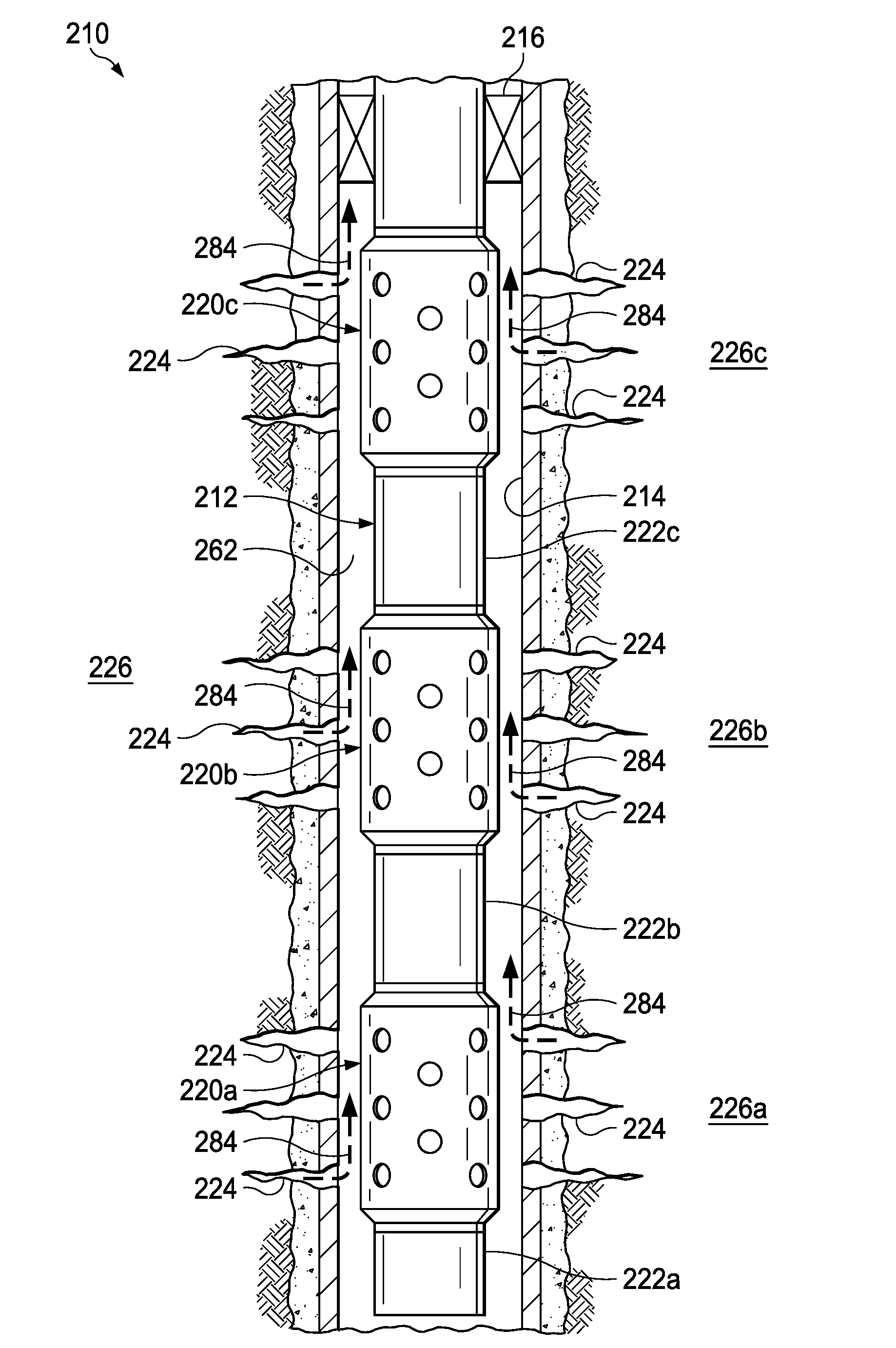
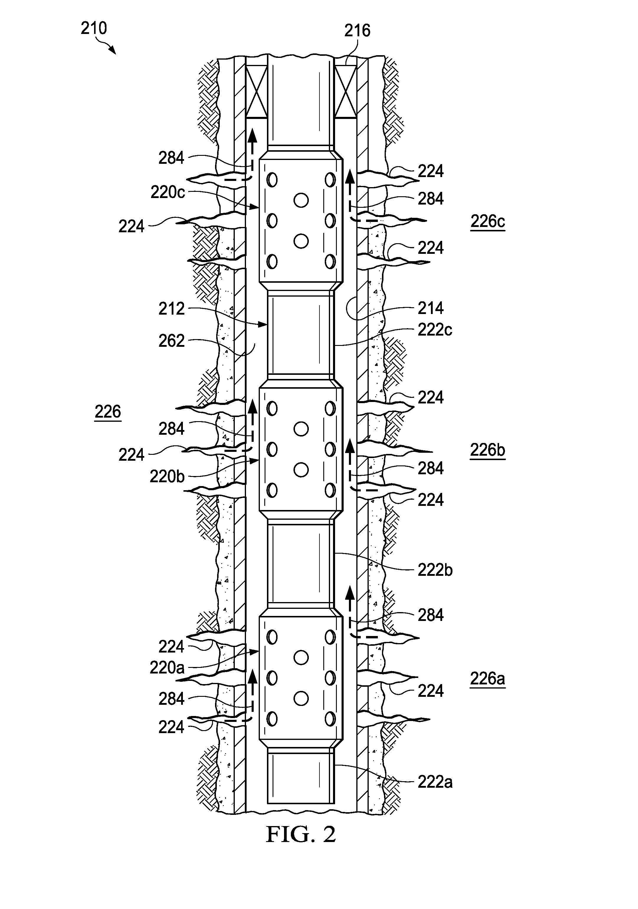
[0067]A system comprising:[0068]at least one shock sensing subassembly having a sensor operable to measure a transient response of a characteristic of a formation following a stimulation event; and[0069]a modeling subsystem having:[0070]a processor;[0071]a communications interface for receiving the measured transient response; and[0072]a memory including instructions to direct the processor to generate a predicted transient response of the characteristic;[0073]wherein the modeling subsystem is operable to receive the measured transient response, compare the measured transient response to the predicted transient response, and update the instructions based on a difference between the measured transient response and the predicted transient response.

example 2

[0074]The system of example 1, wherein the shock sensing subassembly further comprises a sensor memory operable to record and store the measured transient response, and a power source to provide power to the sensor and the sensor memory.

example 3

[0075]The system of example 1 or 2, wherein the modeling subsystem is operable to update the instructions in response to one of: user input of the measured transient response, receiving the measured transient response via a wired communications interface, and receiving the measured transient response via a wireless communications interface.


PUM


Abstract

The disclosed embodiments include a system and method in which a plurality of shock sensing subassemblies are arranged within the tool string to monitor the transient response of formation characteristics to various stimuli, including changes in pressure and temperature of a region of a wellbore that is nearby the formation. The systems and methods involve gathering measurements that reflect the transient response and comparing the measured data to predicted data. The results of the comparison can be used to determine formation properties and to refine and improve modeling processes used to generate the predicted data.

Description

1. FIELD OF THE INVENTION[0001]The present disclosure relates generally to the validation of models for predicting a transient response of a subterranean formation, and more specifically to methods and systems for validating such models by operating shock sensing subassemblies that monitor the transient response of the formation in response to certain stimuli as viewed in terms of, for example, the rate of change of pressure in a portion of the formation.2. DISCUSSION OF THE RELATED ART[0002]As the process for forming wells to recover oil and gas becomes more complex, the ability to accurately predict the formation response to a variety of stimuli is highly beneficial in refining well formation processes, estimating formation properties adjacent a wellbore, and identifying locations for additional wells.[0003]Validating a model may be time consuming, however, because many of the tests used to yield data about the formation properties, such as drill stem testing and shut-in testing, ...

Claims


Application Information

Patent Timeline
IPC IPC(8): E21B47/06G06F17/50G01V11/00E21B43/116E21B49/08
CPCE21B47/06E21B43/116E21B47/065E21B49/08E21B43/14G06F17/5009E21B33/12E21B49/00G01V11/002E21B49/003G06F30/20E21B47/07
Inventor RODGERS, JOHN P.GLENN, TIMOTHY S.SERRA, MARCOBURLESON, JOHN
Owner HALLIBURTON ENERGY SERVICES INC
Learn More