
Disposable Sanitary Tray and Bedside Tables

a technology of bedside tables and sanitary tray, which is applied in the direction of variable height tables, furniture parts, and containers preventing decay, etc., can solve the problems of requiring enormous amounts of time-intensive labor, difficult to establish the corresponding figures for other settings, and inability to know,

Inactive Publication Date: 2017-02-02
KOVACS STEVEN GABOR
View PDF4 Cites 6 Cited by
  • Summary
  • Abstract
  • Description
  • Claims
  • Application Information

AI Technical Summary

Benefits of technology

The patent describes a small device that can be attached to a cartridge / tray to detect the presence of harmful bacteria and antibiotic-resistant pathogens. The device has a peel-away film surface that can be controlled, and the film has texturing or microchannels to improve the flow of anti-microbial compounds or microbes. The technical effect of this invention is to provide an effective tool for detecting and eliminating harmful bacteria.

Problems solved by technology

Obviously, the corresponding figures for other settings are very difficult to establish but given the efforts at hygiene made in the healthcare setting compared to the efforts elsewhere it seems likely that the true, unknowable, figures are much worse.
Many of these require enormous amounts of time-intensive labor, others have financial costs.
For example, cork is much more likely to harbor microorganic life than plastic, but any surface may become contaminated with the passage of too much time.
Cleaning protocols in use appear to be inadequate given the high prevalence found in hospital environments of not just the two pathogens above but multi-drug resistant Acinetobacter baumannii (MDR) and others.
It is rather frightening to consider the home or hotel environment where there are no trained personnel available to combat the spread of pathogens.
However, this curtain is not for handling, it is not for support of food trays, canteens, containers, personal devices or the like, and it lacks any support structures such as a firm backing layer or a table structure, a base, etc.
It also lacks any suggestion, or even any reason why a shower curtain might be combined with a bedside table.

Method used


Image

  • Disposable Sanitary Tray and Bedside Tables
  • Disposable Sanitary Tray and Bedside Tables
  • Disposable Sanitary Tray and Bedside Tables

Examples


fourth embodiment

[0152]FIG. 9 is a side (partially cutaway) view of a core bedside table element of the invention, showing the arm of the bedside table extended and with no base shown, for clarity. This device looks very different from known prior art devices. Main unit 400 can have the tray attached at one end (by means of tines 402 which appear as one because they lined up in this illustration) or by means of other attachment devices.

[0153]Latch 404 may be seen to provide a unique shape for easy fastening and unfastening, as well as being secure: this latch is adapted for the use of the disposable tray with the connector (tines in this embodiment) which hold the tray to the rest of the table.

[0154]Pivot / lock 406 allows the arm segments, such as arm segment 408 or 414, to be rotated so that the tray is held in any desired location, and yet be locked once the various parts are in that location.

[0155]Recess 410 serves several purposes, such as weight and material reduction and providing an easier gri...

fifth embodiment

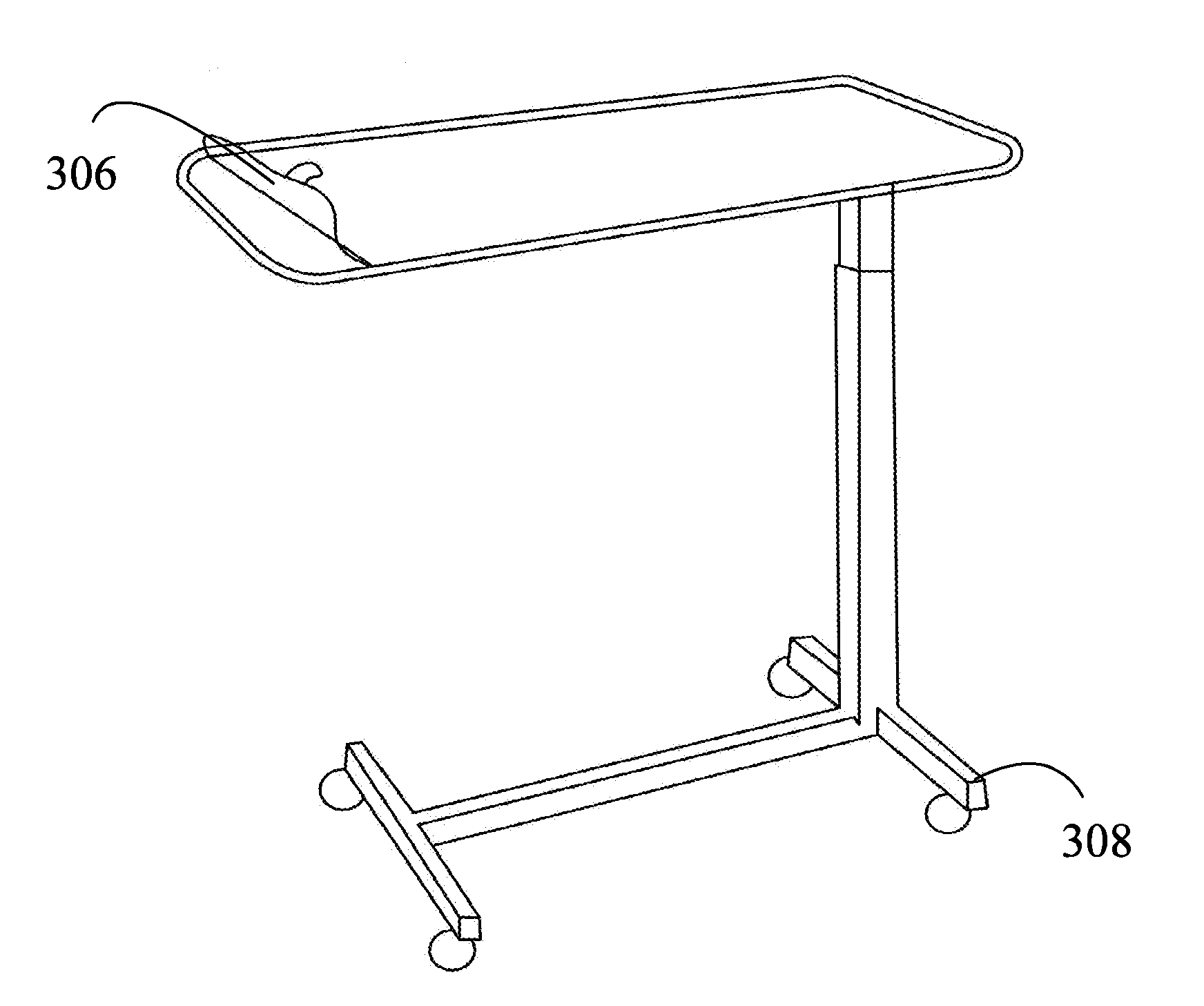
[0157]FIG. 10 is a side view, partially cutaway, of the bedside table of the invention, showing the floor base unit for support. Floor base 520 has an elongated projection which provides leverage for stability. The floor base is also heavy, being made of solid metal or the like, so as to provide weight for additional stability.

[0158]Forks 522 (again seen side on) are dimensioned and configured, and tray 524 is likewise dimensioned and configured, so as to engage to one another mechanically, for example, the tines 522 may extend under the tray into raised areas, into springs, holes, etc in order to secure them together. The tines / connector may provide a solid feel to the tray, allowing thinner tray construction (the tray may be disposable) without sacrificing a feeling of stability.

[0159]Connector 526 (a power cord in the embodiment illustrated) may plug into a standard wall outlet.

sixth embodiment

[0160]FIG. 11 is a side, partially cutaway view of the bedside table according to the invention, showing the wall mounts such as might be used in an institutional setting.

[0161]Wall / floor 630 may be used to support wall rail / wall track 632 (or in preferred embodiments such as that depicted, more than one track) which in turn supports connector 634, which in turn is secured to the piston portion of the core unit. This embodiment may be preferable in institutional settings such as care facilities or health care facilities in which beds may be moved and rooms rearranged and yet the device should be flexibly employable in the same room in a new spot, and the device should be fastened down. It may be preferable for other reasons as well to have a hospital device mounted to a wall.

[0162]This standardized rail may also be a data rail, which allows equipment to slide along the rail freely and yet maintain a data connection between the equipment mounted on the rail and the internet or other ...


PUM

PropertyMeasurementUnit
weightaaaaaaaaaa
voltageaaaaaaaaaa
voltage conductivityaaaaaaaaaa

Abstract

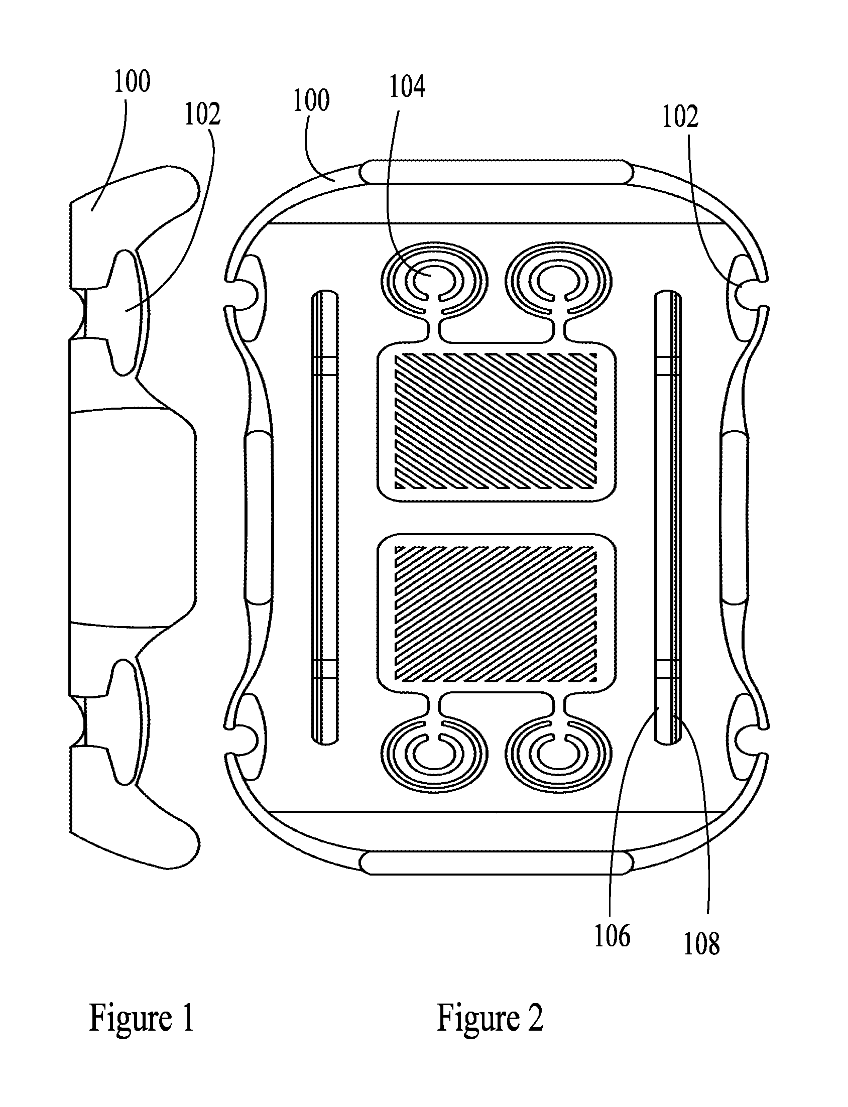
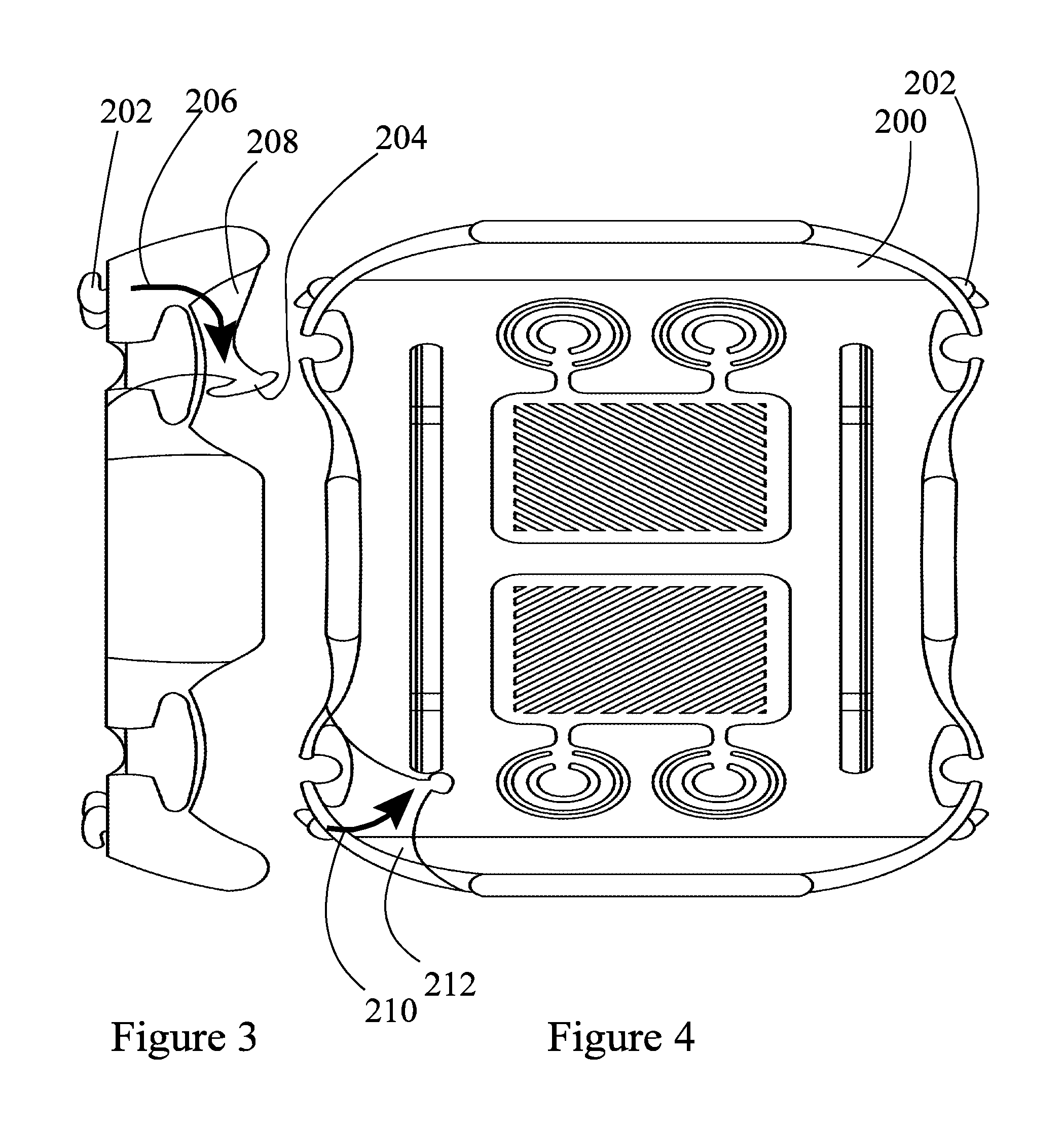
The present invention teaches a bedside table with a disposable hygienic tray which has thereon multiple layers of film. Each layer of film in turn has adhesive, or anti-bacterial compounds, or bacterial detection compounds, or combinations thereof. In use, for example in a hospital, health care setting, home care setting or for home or many other contexts of use, each layer is removed in sequence, exposing a new layer underneath. After a suitable period of usage, the new layer is in turn removed to expose yet another later. When the final layer is removed the disposable tray is removed from the bedside table and replaced with a fresh tray. In embodiments, the core bedside table unit may sit on the floor, mount to a wall rail, or may have a projection dimensioned and configured to pass between the bottom of a mattress and the top of a box spring.

Description

CROSS-REFERENCE TO RELATED APPLICATIONS[0001]The application claims the priority and benefit of previously filed and presently co-pending U.S. Provisional Application No. 62 / 142,785 filed on Apr. 3, 2015 in the name of the same inventor Steven Gabor Kovacs and having the same title, the entirety of which is incorporated herein by this reference.FIELD OF INVENTION[0002]This invention relates generally to disposable tray tables of the caddy or container type, and in particular to the use of compounds having anti-bacterial / bacteria detection properties on multiple peelable layers of a disposable tray fitted to a bedside / sofaside / chairborne table adapted to the tray and to the bed, as well as diverse accessories.STATEMENT REGARDING FEDERALLY FUNDED RESEARCH[0003]This invention was not made under contract with an agency of the US Government, nor by any agency of the US Government.BACKGROUND OF THE INVENTION[0004]While sneezing and coughing are commonly imagined to be the leading causes o...

Claims


Application Information

Patent Timeline
Patent Type & Authority Applications(United States)
IPC IPC(8): A47G19/03A47G23/06B65D81/26A61L2/03A47B9/06A47B23/04A61L2/232A61L2/10B65D1/36A47B13/08
CPCA47G19/03B65D1/36A47G23/06B65D81/264A47B13/086A47B13/081A47B2023/047A47B23/046A61L2/232A61L2/10A61L2/03A47G2023/0658A47B9/06B65D1/34A47G2400/022
Inventor KOVACS, STEVEN GABOR
Owner KOVACS STEVEN GABOR
Learn More