
Dimming circuit

a technology of dimming circuit and dimming device, which is applied in the direction of lighting apparatus, electrical equipment, light sources, etc., can solve the problems of maximum five lamp devices being driven by active methods

Inactive Publication Date: 2017-01-26
LG INNOTEK CO LTD
View PDF2 Cites 1 Cited by
  • Summary
  • Abstract
  • Description
  • Claims
  • Application Information

AI Technical Summary

Benefits of technology

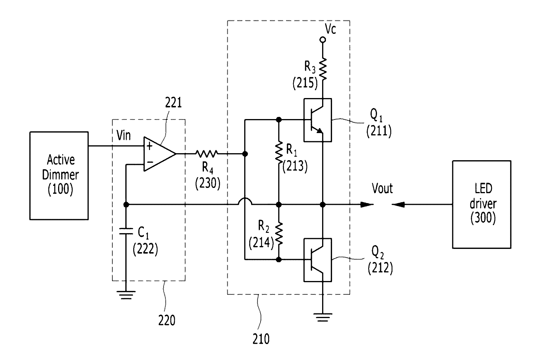
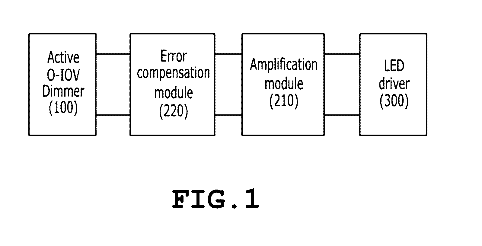
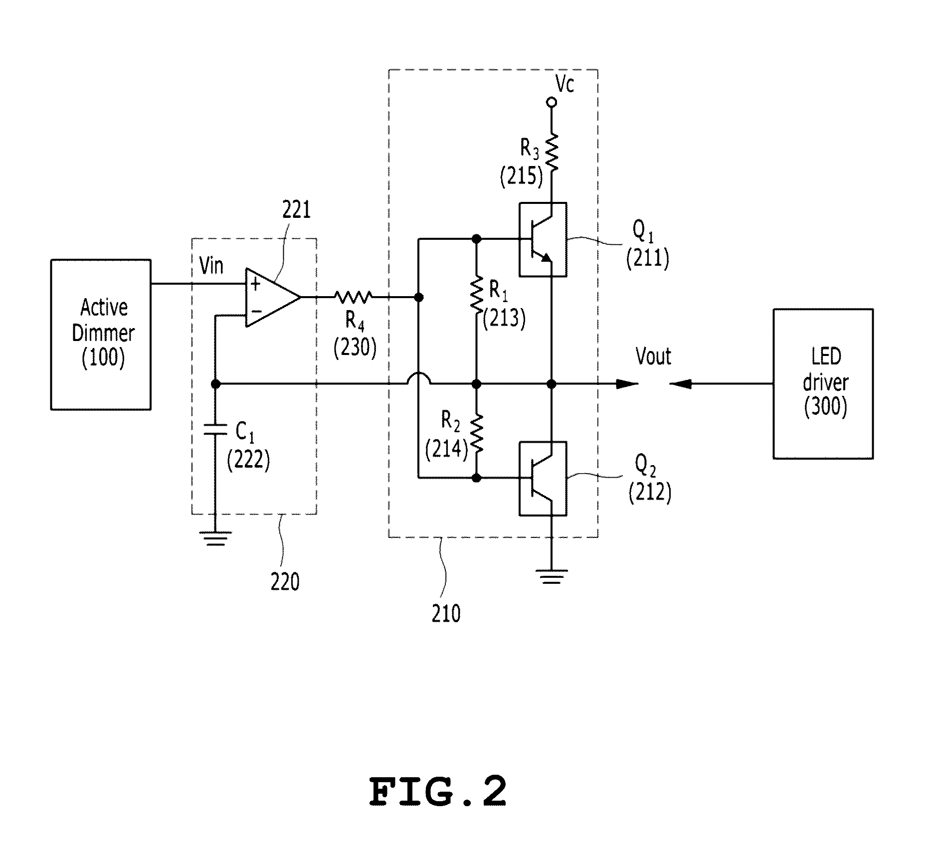
The present invention provides a dimming circuit that can control multiple lamp devices simultaneously and correct errors or distortion through an error compensation module. The circuit includes an amplification module for amplifying the output current of an active dimmer and an error compensation module for correcting errors or distortion. The amplification module and error compensation module are connected in a feedback form. The amplification module can control output power to match input power and may include a push-pull amplifier or a class B amplifier. The error compensation module includes a comparator and a first capacitor. The circuit can be used in various technical applications such as in lighting control systems.

Problems solved by technology

Accordingly, the active method has a disadvantage in that only a maximum of five lamp devices can be driven.

Method used


Image

  • Dimming circuit
  • Dimming circuit
  • Dimming circuit

Examples


Embodiment Construction

[0022]Hereinafter, a “dimming circuit” according to an embodiment of the present invention is described in detail with reference to the accompanying drawings. Embodiments to be described are provided in order for those skilled in the art to easily understand the technical spirit of the present invention, and the present invention is not restricted by the embodiments. Furthermore, contents represented in the accompanying drawings have been diagrammed in order to easily describe the embodiments of the present invention, and the contents may be different from forms that are actually implemented.

[0023]Elements to be described herein are only examples for implementing the embodiments of the present invention. Accordingly, in other implementations of the present invention, different elements may be used without departing from the spirit and scope of the present invention.

[0024]Furthermore, an expression that some elements are “included” is an expression of an “open type”, and the expressi...


PUM


Abstract

A dimming circuit includes an active dimmer configured to apply input power Vin to an amplification module or an error compensation module, the amplification module configured to amplify an output current of the active dimmer, and the error compensation module configured to correct an error or distortion of the amplification module. The amplification module and the error compensation module are connected in a feedback form.

Description

CROSS REFERENCE TO RELATED APPLICATION[0001]The present application claims the benefit of Korean Patent Application No. 10-2015-0103026 filed in the Korean Intellectual Property Office on Jul. 21, 2015, the entire contents of which are incorporated herein by reference.BACKGROUND OF THE INVENTION[0002]1. Technical Field[0003]The present invention relates to a dimming circuit including an active dimmer for applying input power Vin to an amplification module or an error compensation module, an amplification module for amplifying the output current of the active dimmer, and an error compensation module for correcting an error or distortion of the amplification module, wherein the amplification module and the error compensation module are connected in a feedback form.[0004]2. Description of the Related Art[0005]A light-emitting diode (LED) is a kind of semiconductor device for converting electric energy into light. An LED has advantages of low consumption power, a semi-permanent lifespan...

Claims


Application Information

Patent Timeline
IPC IPC(8): H05B33/08H05B44/00
CPCH05B33/0845H05B45/10
Inventor LEE, JONG HYUNYOON, DONG KEUNKIM, JUNG TAECHO, SHIN
Owner LG INNOTEK CO LTD
Learn More