
Base terminal block and auxiliary terminal block for switchboards and two-tier terminal block assembly comprising base terminal block and auxiliary terminal block

a technology of auxiliary terminal blocks and switchboards, which is applied in the direction of basic electric elements, coupling device connections, electrical equipment, etc., can solve the problems of increased costs and occupied space, and the size of installation cabinets is also larg

Active Publication Date: 2017-01-26
MORSETTITALA
View PDF41 Cites 14 Cited by
  • Summary
  • Abstract
  • Description
  • Claims
  • Application Information

AI Technical Summary

Benefits of technology

The present invention is a new type of terminal block for connecting electrical wires, which can be coupled in a vertical direction to create a two-tiered block. It also includes an auxiliary terminal block that can be added onto the base terminal block for more wires. This design allows for a more modular and efficient way of connecting electrical wires, especially in switchboards.

Problems solved by technology

It is also known that the increasingly greater demand for connections and branched junctions both in the electrotechnical sector and in the electronics sector, where it is required to direct also the control signals, results in the design of electric switchboards which have increasingly larger dimensions and consequently occupy a greater amount of space in the installation premises, resulting in greater costs due to the larger dimensions also of the installation cabinets.
The technical problem which is posed, therefore, is to provide a terminal block, in particular of the type for wired-circuit switchboards, which allows the connection / branching capacity of the switchboard to be increased without having to increase its dimensions in particular in the longitudinal direction of the width, but preferably also thickness.

Method used


Image

  • Base terminal block and auxiliary terminal block for switchboards and two-tier terminal block assembly comprising base terminal block and auxiliary terminal block
  • Base terminal block and auxiliary terminal block for switchboards and two-tier terminal block assembly comprising base terminal block and auxiliary terminal block
  • Base terminal block and auxiliary terminal block for switchboards and two-tier terminal block assembly comprising base terminal block and auxiliary terminal block

Examples


Embodiment Construction

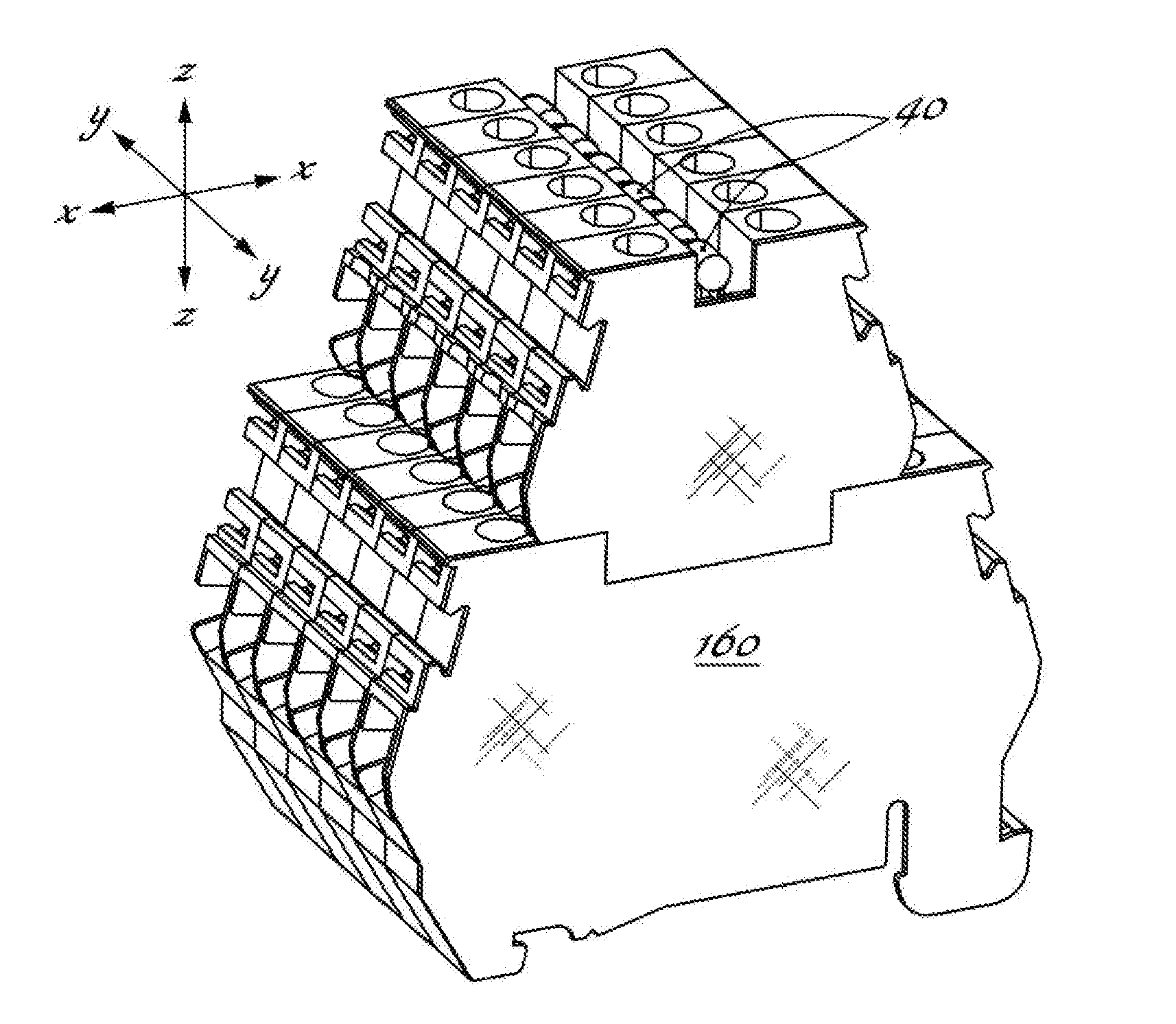
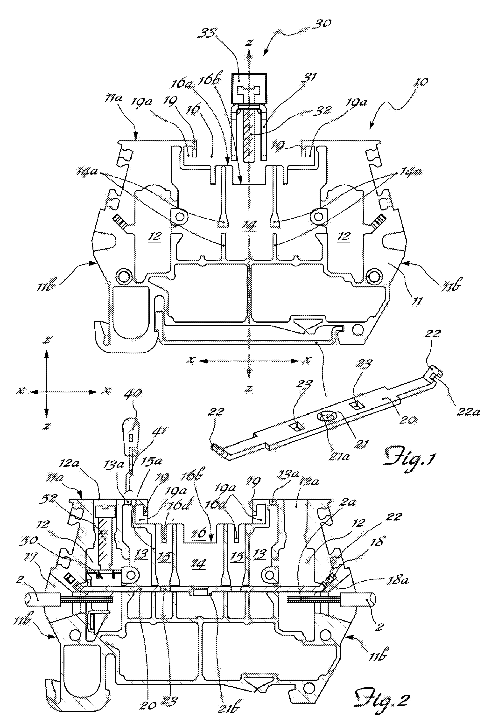
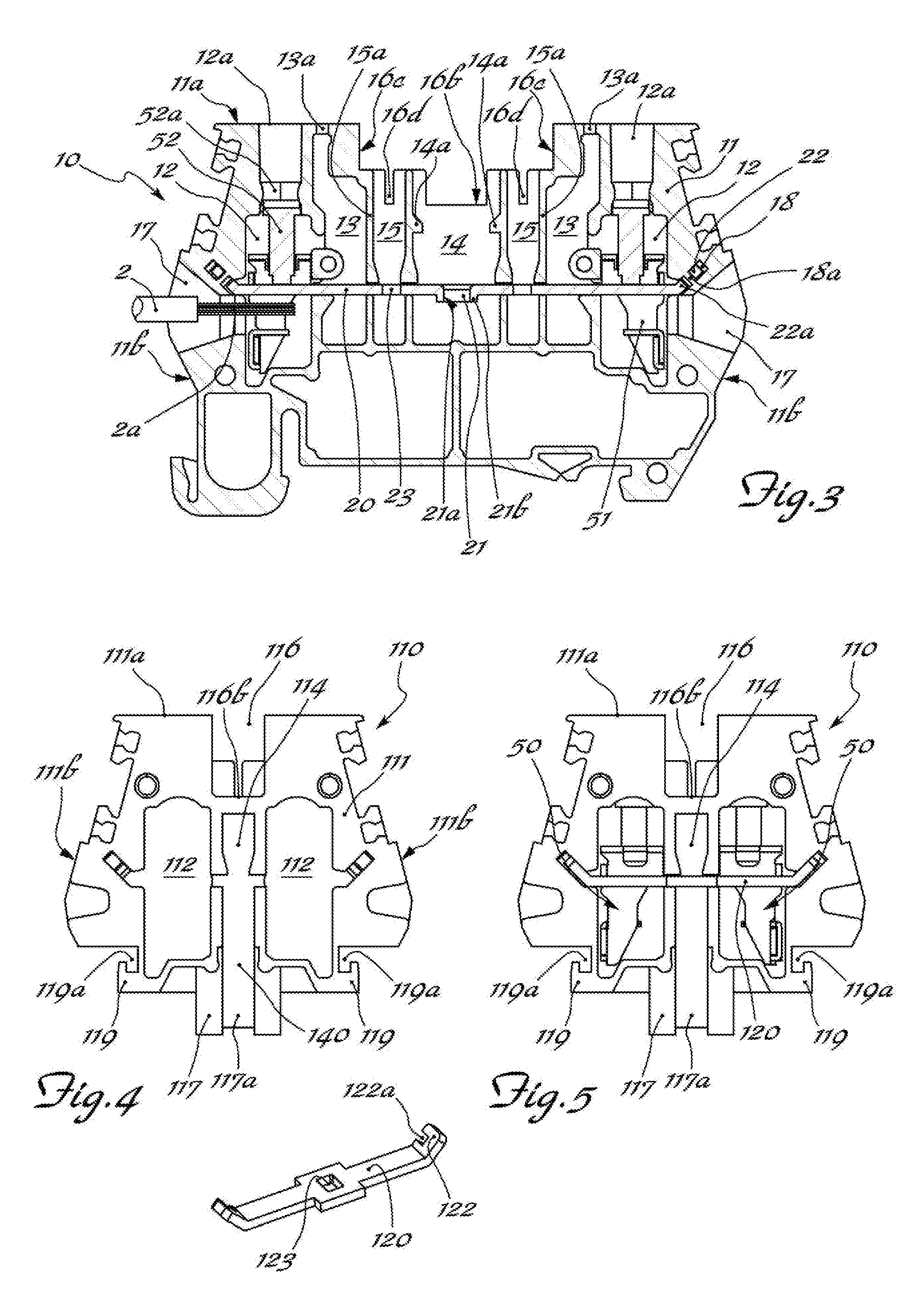
[0032]As shown, for the sake of easier description and without a limiting meaning, a set of three reference axes are assumed, i.e. in the longitudinal direction X-X, corresponding to the lengthwise dimension of the terminal block; transverse direction Y-Y, corresponding to the width or thickness of the terminal block; and vertical direction Z-Z, corresponding to the heightwise dimension of the terminal block and the direction of superimposition of an add-on terminal block on top of a base terminal block, and for easier illustration coinciding with the central vertical axis of the terminal block.

[0033]For the sake of easier description, and using the directional layout shown in the figures by way of example, the following are also assumed: a bottom part corresponding to the part of the base terminal block for coupling with a DIN-standard rail B (FIG. 1) fixed to the electric switchboard (not shown) and a top part, opposite to the first part, corresponding to the visible side of the t...


PUM


Abstract

A switchboard base terminal block for connecting electrical wires comprising an insulating body having one top side and a bottom side opposite in a vertical direction, and at least two respective flanks opposite to each other in a longitudinal direction; wherein inside the body there is formed at least: a first pair of seats; a first space centred on a central vertical axis and bounded in the longitudinal direction by respective first partitions extending parallel to the vertical direction spaced from each other in the longitudinal direction by an amount such as to define a size of the space suitable for housing a jumper of the screw type; an undercut with base formed in the top side of the terminal block, presenting a first central opening for connecting externally the central space for insertion of the respective screw jumper, and means for coupling with corresponding means of an add-on terminal block for forming a two-tier terminal block in the vertical direction wherein said coupling means are adapted for determining a stable and non-decouplable along the vertical direction coupling with the corresponding coupling means of the add-on terminal block.

Description

FIELD OF THE INVENTION[0001]The present invention relates to a switchboard terminal block for connecting electrical wires.BACKGROUND OF THE INVENTION[0002]It is known, in the technical sector relating to the production of switchboards for the wiring of electrical installations, to use terminal blocks designed to be mounted on associated supports, such as DIN-standard rails, and to provide on the front side access to the means—normally of the screw or spring type—for retaining electrical wires to be connected in order to restore continuity of the various sections of the electric circuit; said continuity being achieved by inserting inside a special seat, accessible from the front side, movable contact elements such as protection fuses, electric circuit breakers or jumpers for connecting together two or more adjacent terminal blocks.[0003]It is also known that these connection jumpers may be:[0004]configured with two spring lugs forming the element for coupling inside the seat of the t...

Claims


Application Information

Patent Timeline
IPC IPC(8): H01R25/14H01R9/24
CPCH01R25/142H01R9/2416H01R9/2408H01R9/2675
Inventor PIZZI, GIORDANO
Owner MORSETTITALA
Learn More