
MPI method

a technology of mpi image and image, applied in the field of mpi image, can solve problems such as artefacts in mpi imag

Active Publication Date: 2017-01-26
BRUKER BIOSPIN MRI
View PDF6 Cites 16 Cited by
  • Summary
  • Abstract
  • Description
  • Claims
  • Application Information

AI Technical Summary

Benefits of technology

The invention provides a method for accurately measuring the concentration of magnetic particles in a larger area. This is achieved by performing multiple measurements in different locations and shifting the measurement volume to include the entire area. The method ensures that the reconstructed magnetic particle concentration values outside the measurement volume do not affect the final result. To calibrate the measurements, calibration volumes are selected that overlap with the overscan area. This method allows for more accurate and reliable particle concentration measurements in larger areas.

Problems solved by technology

Although these are not swept over by the field-free region, they nevertheless contribute to the measurement signal due to their rotation and unsharpness of the field-free region.
This can lead to artefacts in the MPI image.

Method used


Image

  • MPI method
  • MPI method
  • MPI method

Examples


Embodiment Construction

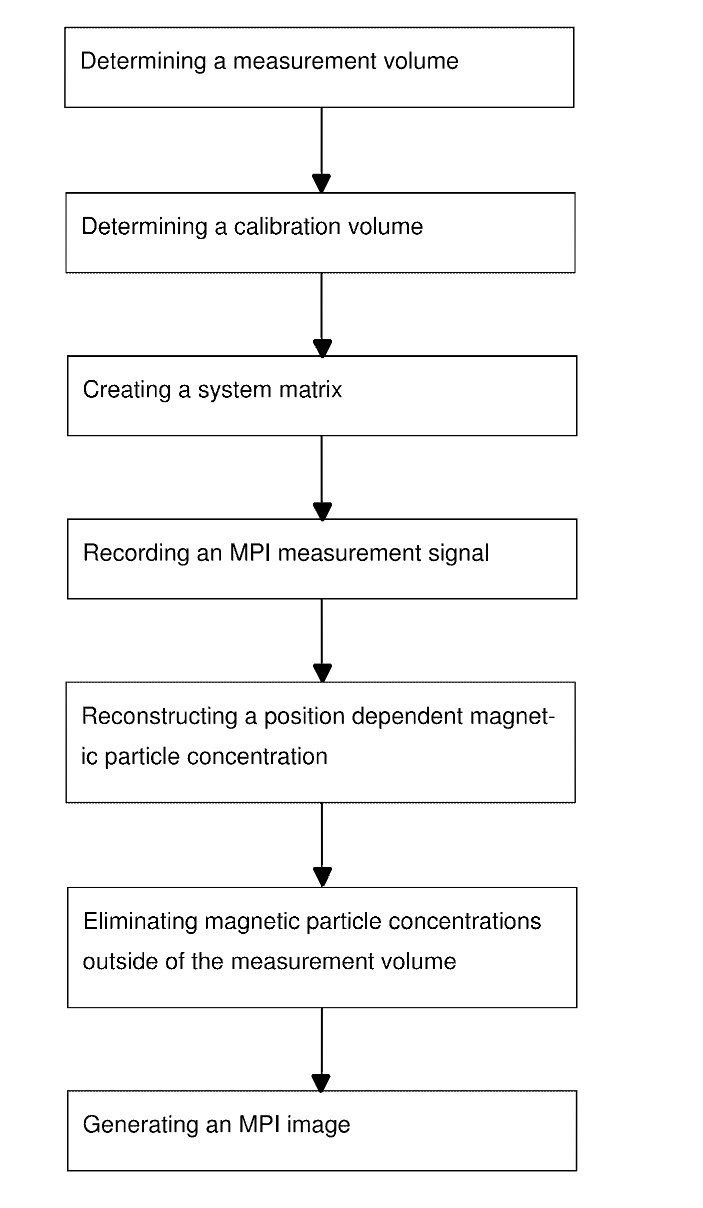
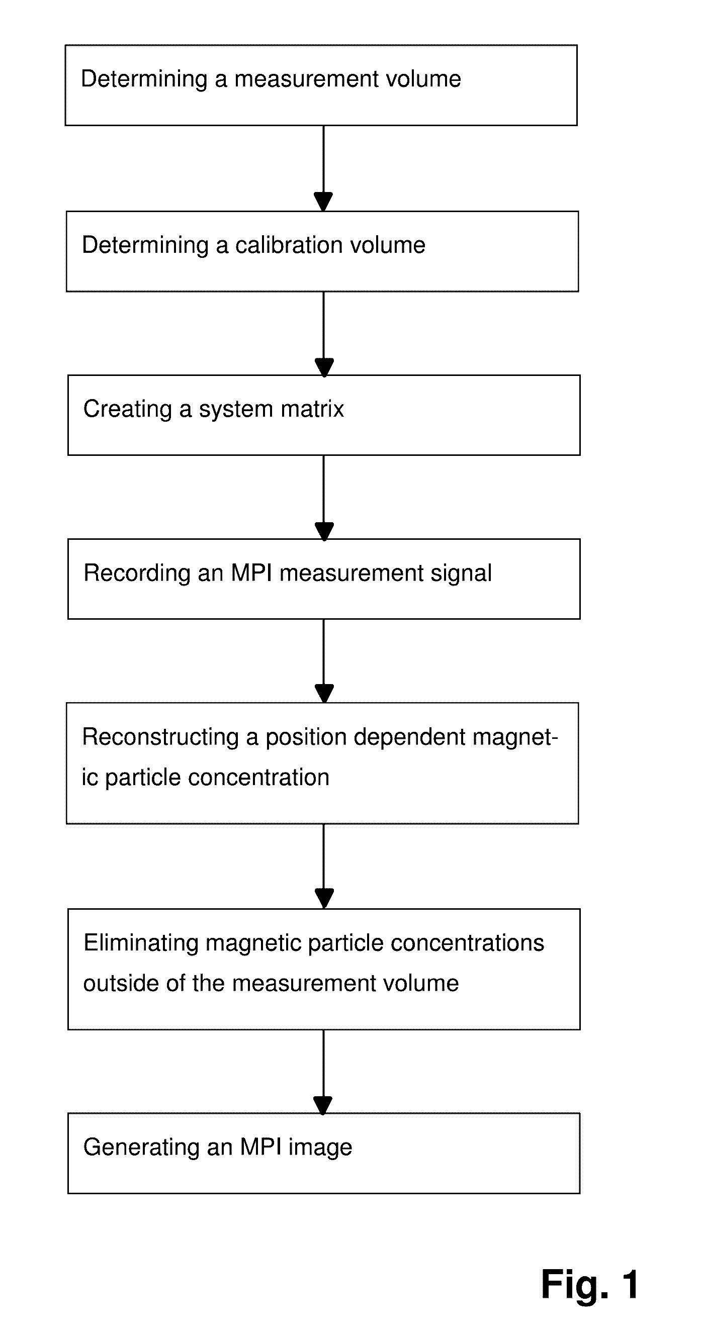
[0044]The process steps of the inventive method given in FIG. 1 are described below:

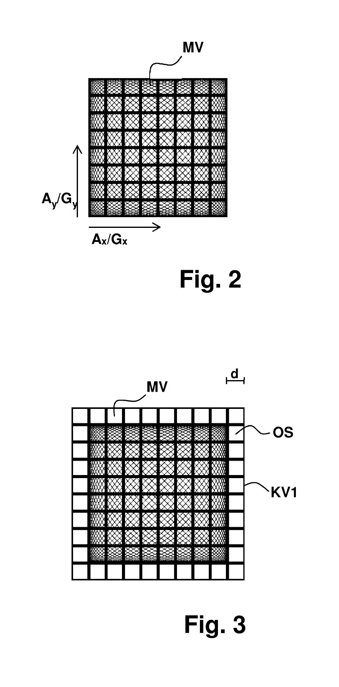
[0045]At first, a user-defined measurement volume and a voxel grid for the measurement volume are selected, in which a field-free region is moved over the individual voxels of the voxel grid of the measurement volume during subsequent MPI measurement. Towards this end, corresponding magnetic fields (gradient fields, excitation fields, focus fields) are applied, wherein the size of the measurement volume depends on the amplitude of these magnetic field, or the magnetic fields are adjusted such that the desired size of the measurement volume is obtained.

[0046]For establishing a system matrix, calibration is performed within a previously selected calibration volume which is larger than the measurement volume (calibration volume=measurement volume+overscan area) and contains it. A voxel grid different from the voxel grid of the measurement volume can then be selected for the overscan area or the voxel gr...


PUM


Abstract

An MPI method determines calibration and measurement volumes, wherein the calibration volume is larger than the measurement volume and the overall measurement volume is arranged within the calibration volume. Calibration signals are detected and a system matrix S is created. An MPI measuring signal u is recorded, a location-dependent magnetic particle concentration c with magnetic particle concentration values ci within the calibration volume is reconstructed and the magnetic particle concentration values ci are associated with voxels in the calibration volume. Magnetic particle concentration values ci which were associated with voxels outside of the measurement volume are discarded and an MPI image is generated which exclusively contains magnetic particle concentration values ci which were associated with the voxels within the measurement volume. MPI image data are thereby generated with little artefacts within a short time even in case of high magnetic particle densities outside of the measurement volume.

Description

[0001]This application claims Paris convention priority from DE 10 2015 214 071.7 filed Jul. 24, 2015 the entire disclosure of which is hereby incorporated by reference.BACKGROUND OF THE INVENTION[0002]The invention concerns an MPI method for localizing magnetic particles within a test sample, wherein a location-dependent magnetic field is applied which has a field-free region, the method comprising the following steps:[0003]determining a calibration volume and a measurement volume, wherein the calibration volume is larger than the measurement volume and wherein the overall measurement volume is arranged within the calibration volume;[0004]detecting calibration signals Sj and creating a system matrix S from the calibration signals Sj;[0005]recording an MPI measuring signal u (MPI time signal or MPI frequency spectrum obtained through Fourier transformation of the MPI time signal), wherein through application of the magnetic control field, the field-free region is moved through the m...

Claims


Application Information

Patent Timeline
Patent Type & Authority Applications(United States)
IPC IPC(8): A61B5/05A61B5/00G01R33/12
CPCA61B5/0515A61B5/7257G01R33/1276A61B5/7203
Inventor WEBER, ALEXANDER
Owner BRUKER BIOSPIN MRI
Learn More