
System and method for optimizing an aircraft trajectory

a technology of aircraft trajectory and optimization method, applied in process and machine control, energy saving arrangements, instruments, etc., to achieve the effect of reducing the workload of atcs, saving fuel and time, and reducing fuel burn

Active Publication Date: 2017-01-19
DOUBLE BLACK AVIATION TECH L L C
View PDF5 Cites 11 Cited by
  • Summary
  • Abstract
  • Description
  • Claims
  • Application Information

AI Technical Summary

Benefits of technology

[0009]In accordance with the invention, systems and methods are provided for generating a plurality of conflict-free flight trajectories that best suits one or more selected operational requirements of a pilot, an AOC, an ATC, etc. The plurality of conflict-free flight trajectories provide more than separation assurance from other aircraft. The plurality of flight trajectories is free of conflicts such as other aircraft, weather events, no-fly zones, and other restrictions. In addition, the conflict-free flight trajectories are vetted or calculated based on one or more parameters. For example, flight trajectories may be generated based on fuel efficiency, time efficiency, optimum airspeed, and combinations of the same. The resulting plurality of conflict-free flight trajectories saves fuel and time, offers flexibility to pilots and airlines, reduces the workload of ATCs, reduces fuel burn, reduces noise, reduces the emission of carbon dioxide, and reduces nitric oxide by requiring fewer interventions.
[0018]Another example of an EMW is when the pilot wishes to avoid spending time at an altitude (or range of altitudes) where aircraft structural icing occurs. By inserting EMWs into the trajectory the instant aircraft could avoid spending time at altitudes where icing conditions exist. In yet another example the aircraft's total energy could be managed to avoid possible injury to passengers and crew by being within the optimum speed for penetration of turbulent airspace. By inserting EMWs into the trajectory the instant aircraft can travel at the proper speed for turbulent conditions and avoid excessively violent gyrations associated with flying too fast in turbulent air.

Problems solved by technology

For example, if the instant aircraft determines a flight trajectory that passes within the SAI assigned to another aircraft, then there is a conflict because the instant aircraft is passing too close to the other aircraft.

Method used


Image

  • System and method for optimizing an aircraft trajectory
  • System and method for optimizing an aircraft trajectory
  • System and method for optimizing an aircraft trajectory

Examples


Embodiment Construction

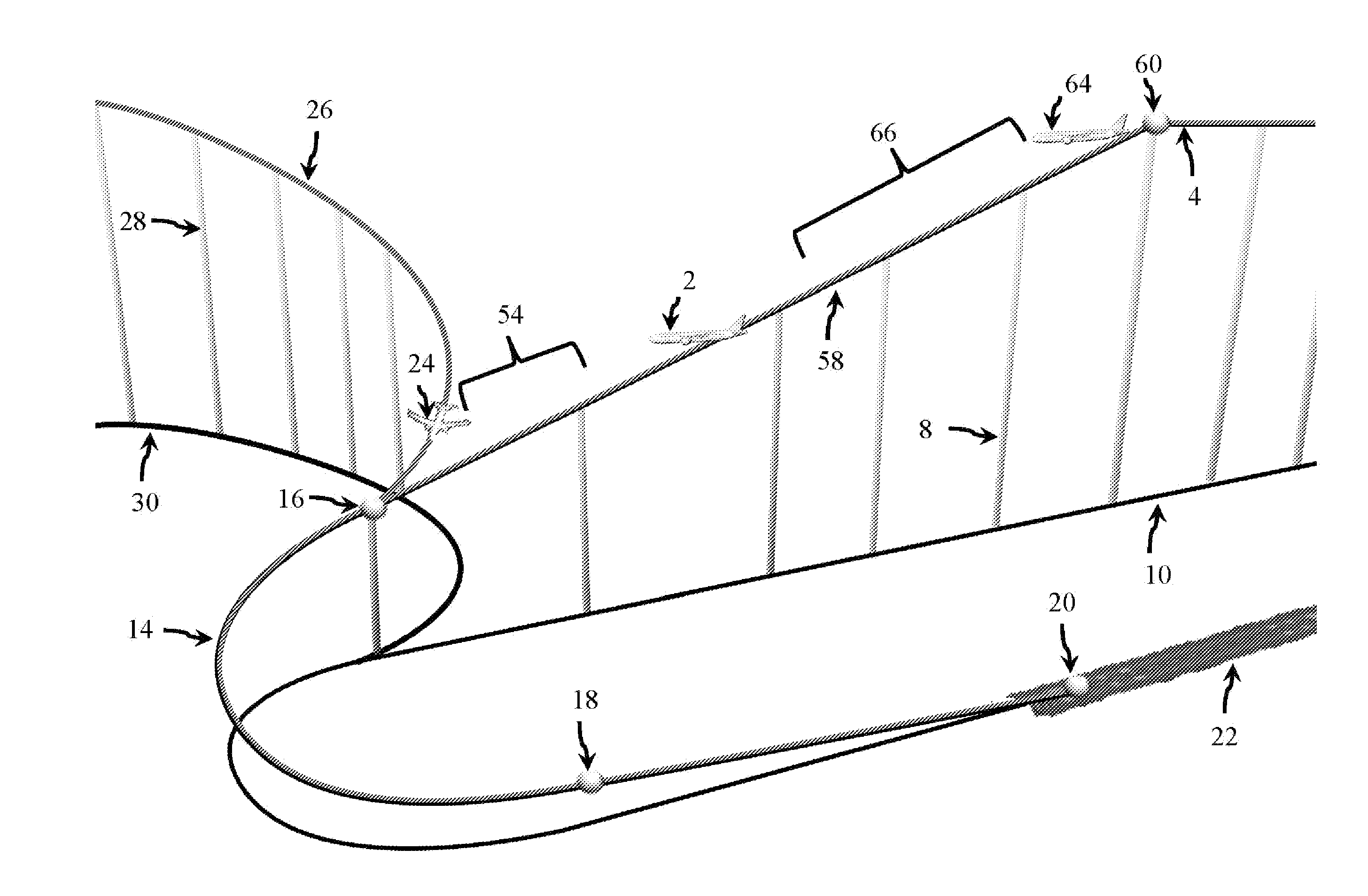
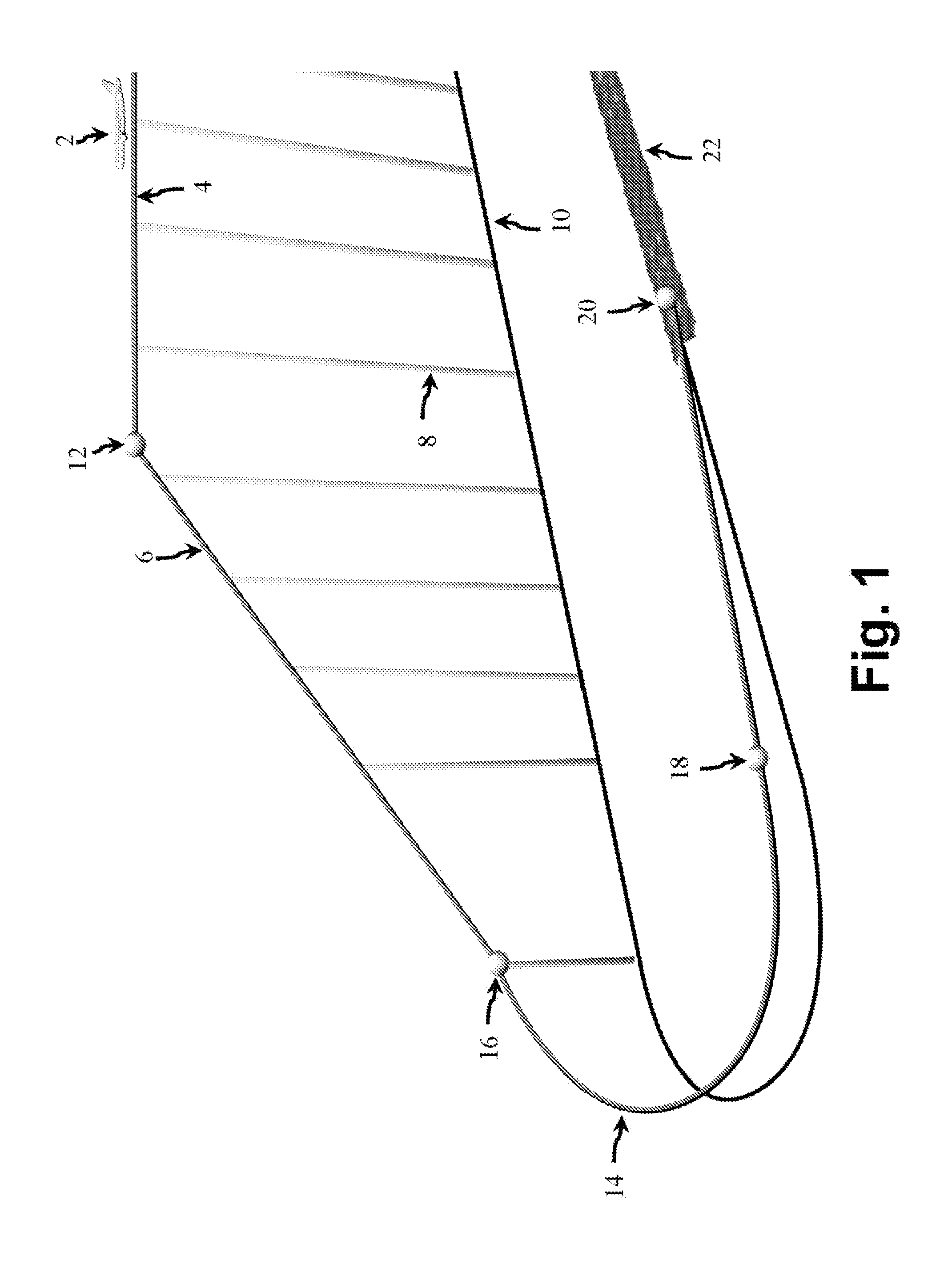
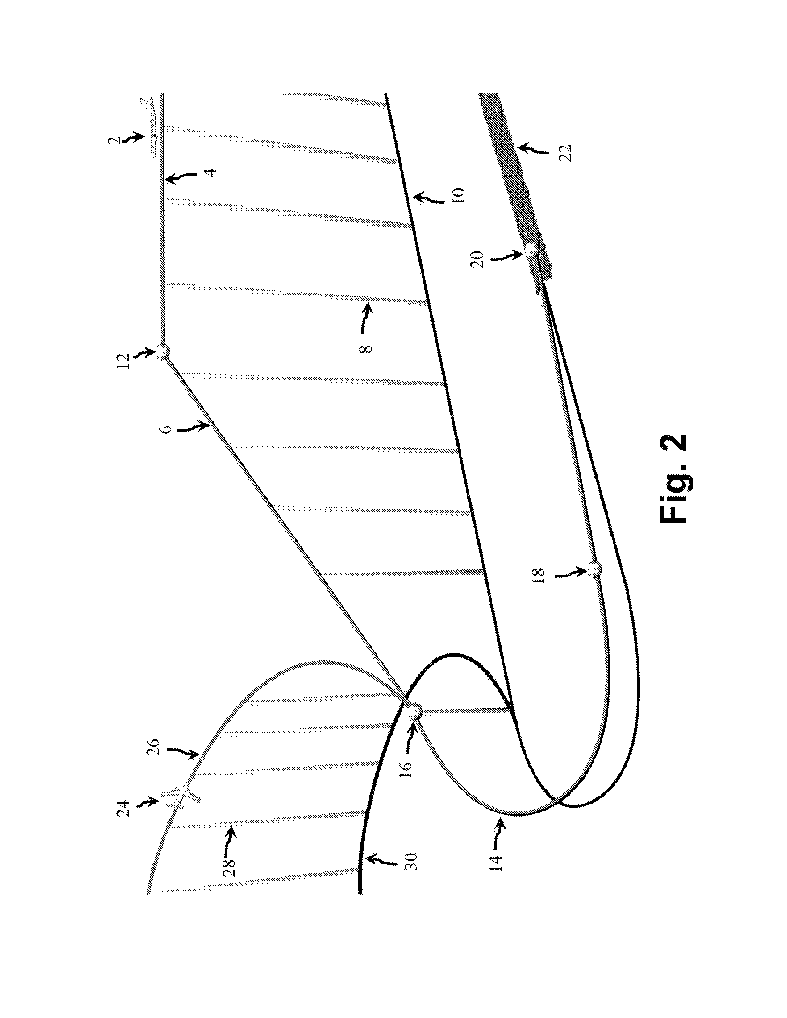
[0053]Referring to FIGS. 1-3, several prior art scenarios are provided to highlight the shortcomings of existing aviation systems that will often require an air traffic control (ATC) system to intervene and instruct a pilot to change the aircraft's flight trajectory. FIG. 1 shows an aircraft 2 that is leaving an en route phase 4 of the aircraft's flight trajectory and entering a descent phase 6. In this scenario, there are no other aircraft in the immediate area. During the aircraft's en route phase 4, the aircraft 2 is flying at a generally constant altitude. Flight path shadow lines or altitude bars 8 are provided to show the relative altitude of the aircraft's flight trajectory at periodic intervals. The lower ends of the altitude bars 8 create a ground path 10 of the flight path that shows where the aircraft 2 is flying above the ground.

[0054]The transition between the en route phase 4 of the aircraft's flight trajectory and the descent phase 6 is called the Top of Descent (TOD)...


PUM


Abstract

Systems and methods of the present invention are provided to generate a plurality of flight trajectories that do not conflict with other aircraft in a local area. Interventions by an air traffic control system help prevent collisions between aircraft, but these interventions can also cause an aircraft to substantially deviate from the pilot's intended flight trajectory, which burns fuels, wastes time, etc. Systems and methods of the present invention can assign a standard avoidance interval to other aircraft in the area such that a pilot's aircraft does not receive an intervention by an air traffic control system. Systems and methods of the present invention also generate a plurality of conflict-free flight trajectories such that a pilot or an automated system may select the most desirable flight trajectory for fuel efficiency, speed, and other operational considerations, etc.

Description

CROSS REFERENCE TO RELATED APPLICATION[0001]This application claims priority to U.S. Provisional Patent Application Ser. No. 62 / 191,573 filed Jul. 13, 2015, which is incorporated herein in its entirety by reference.FIELD OF THE INVENTION[0002]The present invention relates to the systems and methods for generating flight trajectories for aircraft in flight to meet operational requirements, minimize fuel burn, reduce off path vectoring, and minimize the number of level flight segments during climbs and descents.BACKGROUND OF THE INVENTION[0003]The Federal Aviation Administration (FAA) and other Air Navigation Service Providers (ANSPs) around the world maintain air traffic control systems (ATCs) to organize the flow of aircraft traffic in a particular airspace and to avoid conflicts and prevent collisions among airborne aircraft. To accomplish this task, ATCs rely on ground-based radar systems to determine the “state vector” of an aircraft which includes altitude, position, East-West v...

Claims


Application Information

Patent Timeline
Patent Type & Authority Applications(United States)
IPC IPC(8): G08G5/04G08G5/00
CPCG08G5/0008G08G5/045G01C21/20G05D1/0005G08G5/0013G08G5/0021G08G5/0034G08G5/0039G08G5/0052G08G5/0078G08G5/0091G08G5/025G05D1/0676G01W1/00G05D1/0202G08G5/0026G08G5/0043G08G5/0082G08G5/02G08G5/04
Inventor SHAY, RICHARD
Owner DOUBLE BLACK AVIATION TECH L L C
Learn More