
Storage system

a storage system and system technology, applied in the field of storage systems, can solve the problems of increased management costs of the administrator of the computer system

Active Publication Date: 2017-01-19
HITACHI LTD
View PDF1 Cites 4 Cited by
  • Summary
  • Abstract
  • Description
  • Claims
  • Application Information

AI Technical Summary

Benefits of technology

The present invention allows for effective processing of volumes that are copied among physical storage subsystems, regardless of the state of the system or the volumes themselves. This results in improved efficiency and reliability.

Problems solved by technology

One of the drawbacks of introducing a large number of storage subsystems in a computer system is that the management costs by the administrator of the computer system are increased.

Method used


Image

  • Storage system
  • Storage system
  • Storage system

Examples


embodiment 1

(1) Configuration of Computer System

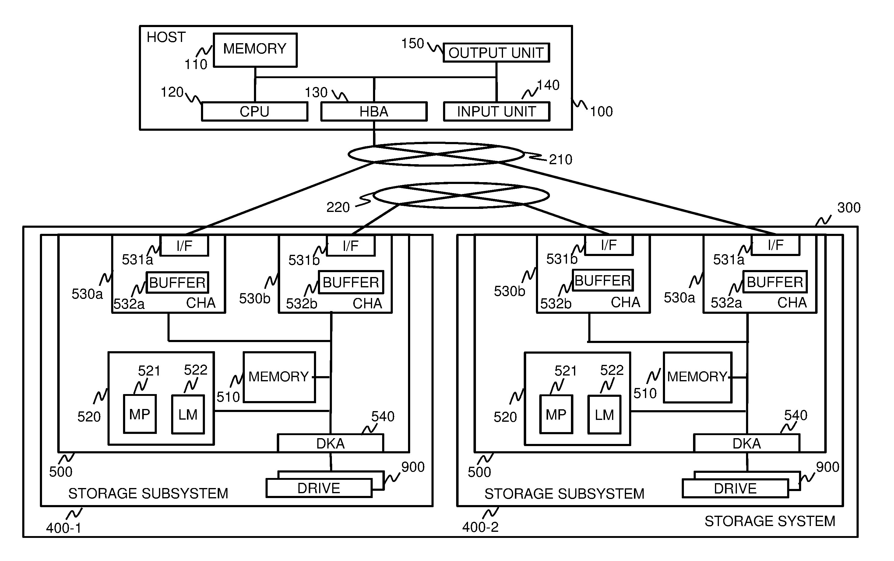
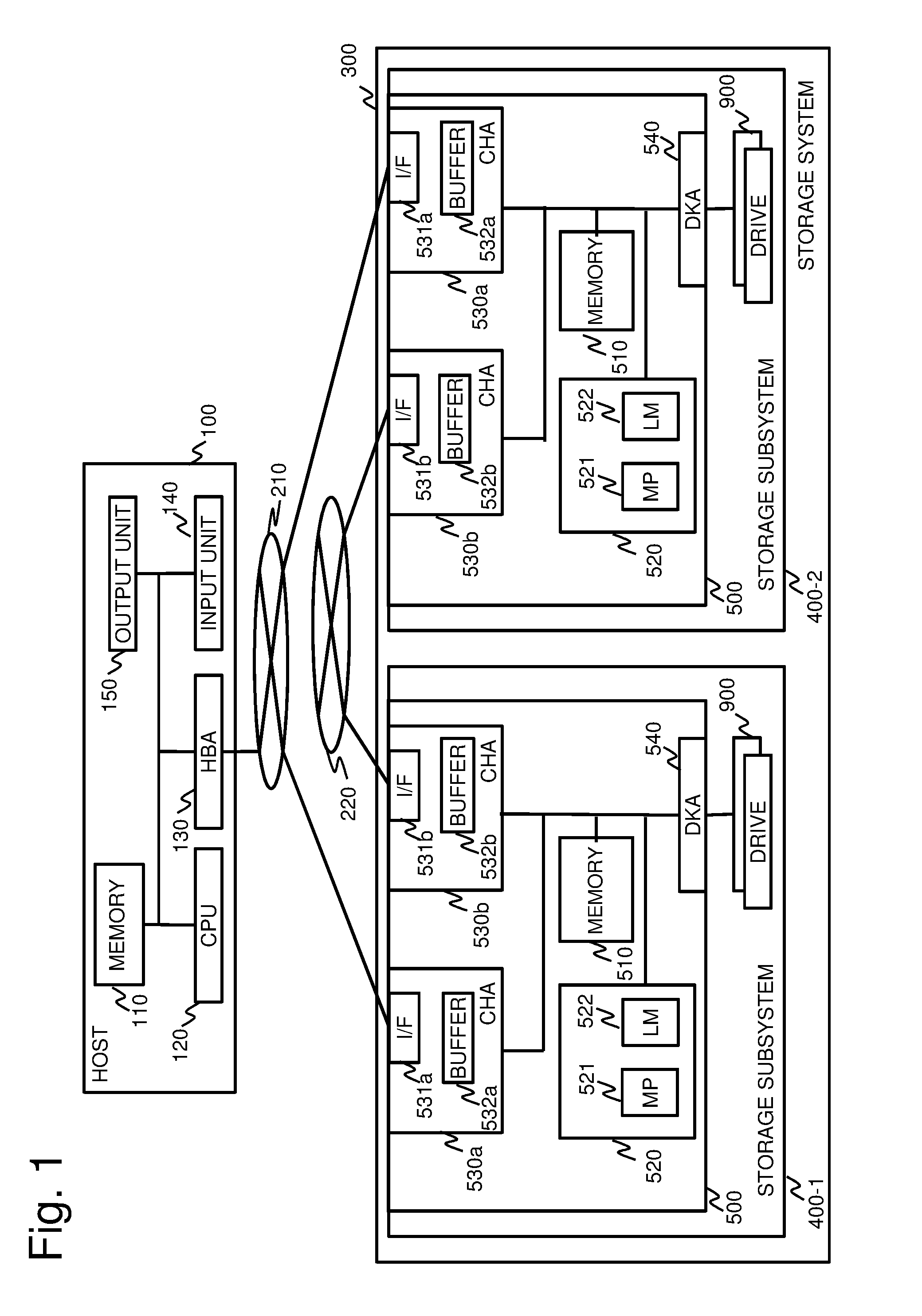
[0039]FIG. 1 is a configuration view of a computer system according to a preferred embodiment of the present invention. A computer system is composed of a host computer 100 (hereinafter abbreviated as “host 100”) and a storage system 300. The storage system 300 is composed of at least two storage subsystems 400-1 and 400-2. The host 100 is connected via a SAN (Storage Area Network) 210 to both storage subsystems 400-1 and 400-2.

[0040]We will now describe a hardware configuration of the storage subsystems 400-1 and 400-2. According to the storage system 300 of the present embodiment, the hardware configurations of both the storage subsystems 400-1 and 400-2 are the same. In the following description, when the storage subsystems 400-1 and 400-2 are referred to without distinguishing the two, they are referred to as the “storage subsystem 400”. However, it is not necessary for the hardware configurations of the storage subsystems 400-1 and 400-2 to b...

modified example

[0171]According to the flow of the process described above, when data designated by the WRITE SAME command is written from the storage subsystem 400-1 to a volume in the storage subsystem 400-2 (or when data designated by the WRITE SAME command is written from the storage subsystem 400-2 to a volume in the storage subsystem 400-1), the WRFBA command had been used. However, the WRFBA command is a command that requires data having the same size as the data write range to be transmitted, even when the same contents is to be written throughout the whole area. Therefore, as a modified example of the embodiment described above, we will describe an example of defining and using a command (hereafter, this command is referred to as “WRITE SAME propagation command”) where the same data is written to all the data write range by transmitting only a small portion (such as one block) of the write data, similar to the WRITE SAME command.

[0172]The WRITE SAME propagation command is a command for ins...


PUM


Abstract

A storage system according to one preferred embodiment of the present invention is composed of at least a first storage subsystem and a second storage subsystem. Write data from a host computer is duplicated to a first volume of the first storage subsystem and a second volume of the second storage subsystem, and the host computer is composed to be able to access both the first volume and the second volume. Attribute information which is information related to an order of write and / or write capability is set for each volume, and when an access command to the volume is received from the host computer, the storage subsystem determines whether I / O to the first volume and / or the second volume is required or not based on the attribute set for each volume.

Description

TECHNICAL FIELD[0001]The present invention relates to a storage system.BACKGROUND ART[0002]Along with the rapid increase in the amount of electronic information handled in companies and other organizations, a large number of storage subsystems are introduced and operated in the IT systems of organizations. One of the drawbacks of introducing a large number of storage subsystems in a computer system is that the management costs by the administrator of the computer system are increased. The art of storage virtualization is adopted widely, in which multiple storages are enabled to be accessed virtually as a single storage with the aim to facilitate management of multiple storage subsystems.[0003]As one embodiment for virtualizing storages, a configuration is proposed where multiple physical storage subsystems are provided to a superior system such as a host computer utilizing the storage subsystem as a single virtual storage subsystem. For example, Patent Literature 1 discloses an art ...

Claims


Application Information

Patent Timeline
Patent Type & Authority Applications(United States)
IPC IPC(8): G06F3/06
CPCG06F3/0619G06F3/0659G06F3/0665G06F3/0689G06F3/06G06F12/00G06F13/10G06F12/0868G06F3/0617G06F3/0635G06F11/2074G06F11/2079G06F11/2069G06F11/16
Inventor TAKEI, TOMOHIROISHIKAWA, YOHEYSAITO, HIDEOTOKORO, KENTAMURA, KEISHIKAWAGUCHI, TOMOHIRO
Owner HITACHI LTD
Learn More