
Axle Load Monitoring System

Inactive Publication Date: 2017-01-19
STRONG BROOKS +1
View PDF37 Cites 24 Cited by
  • Summary
  • Abstract
  • Description
  • Claims
  • Application Information

AI Technical Summary

Benefits of technology

The present invention is an axle load monitoring system for vehicles with multiple axles. The system detects when the vehicle carries too much weight on its primary axles or when the weight on a group of axles exceeds a certain level. It recommends using auxiliary axles to prevent this from happening, while ensuring that the overall weight does not exceed a certain limit. The system also provides information on the status of the auxiliary axles, the weight on the axles, and if there is compliance with applicable rules and regulations. It can also recommend stowed auxiliary axles when they are not needed. The system helps ensure safe and legal driving while carrying the desired amount of weight.

Problems solved by technology

Load-transporting motor vehicles such as dump trucks, refuse trucks, transit concrete mixing trucks, open-bed trucks, utility trucks, military trucks and other vehicles of various types to which a significant load may be added for transport are limited in their load transporting ability by various factors.
Among the challenges faced in employing auxiliary axles, whether it is a pusher axle or a tag axle or a trailing axle, is in first determining whether auxiliary axle use is actually needed and then to what extent and then in determining the down force to be applied to the auxiliary axle (s) deployed and thereby the weight of the vehicle they carry.
And in the equipping of a load-transporting motor vehicle with one or more auxiliary axles, their location and forced loading is commonly based on the typically expected load and the location of the resulting center of gravity of the vehicle and thus not well suited where there is a significant departure from what would be considered a normal load.
And apart from servicing, if a trailing axle is deployed but is actually not needed for additional vehicle support, it should be sufficiently forced downward for trailing axle stability as otherwise it would be serving no useful purpose and could adversely affect the road performance of the vehicle.
Furthermore, when the wheels of an auxiliary axle that is acted on with a significantly low down force passes over sudden elevation changes such as in the case of a pothole or dip in a road surface, there are sudden dynamic forces that can result and are applied to the axle that may not be compatible with the structural design of the axle and its suspension.
Moreover, in the case of a trailing axle there may be insufficient down force with regard to contributing to vehicle braking and roll stability as well as helping to support the vehicle.
Then at the other end of the spectrum, if one of the auxiliary axles whether it is a pusher axle or a tag axle or a trailing axle is down forced such that it accepts more vehicle weight than required to meet weight carrying limits on the primary axles, one or more of the primary axles may lose its ability to adequately perform as intended.
Moreover, the choice of whether to activate or deactivate any auxiliary axles is made even more difficult where the vehicle for example makes multiples stops to either drop off part of a load or pick up additional load before reaching the final destination for off-loading.
But this is not a practical thing to do while on the road and in not knowing how much adjustment is actually needed for proper operation.
Because if this is not done correctly and though the vehicle with the auxiliary axles deployed would appear to be in compliance with all applicable laws, this could be a costly incorrect assumption.

Method used


Image

  • Axle Load Monitoring System
  • Axle Load Monitoring System
  • Axle Load Monitoring System

Examples


Embodiment Construction

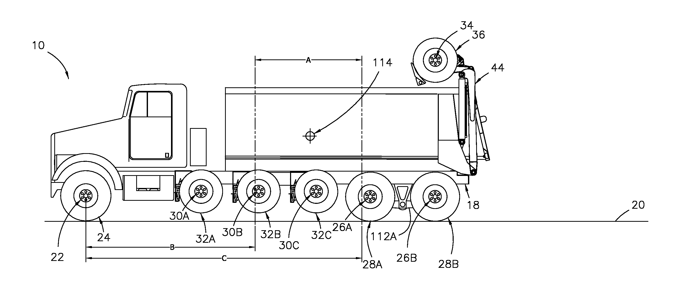
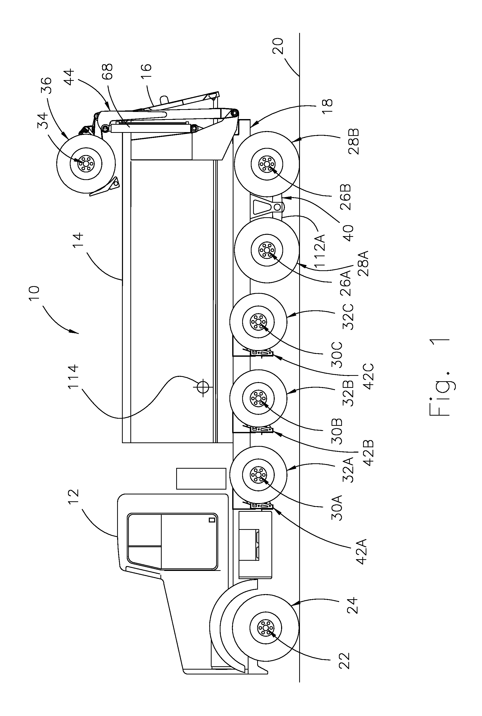
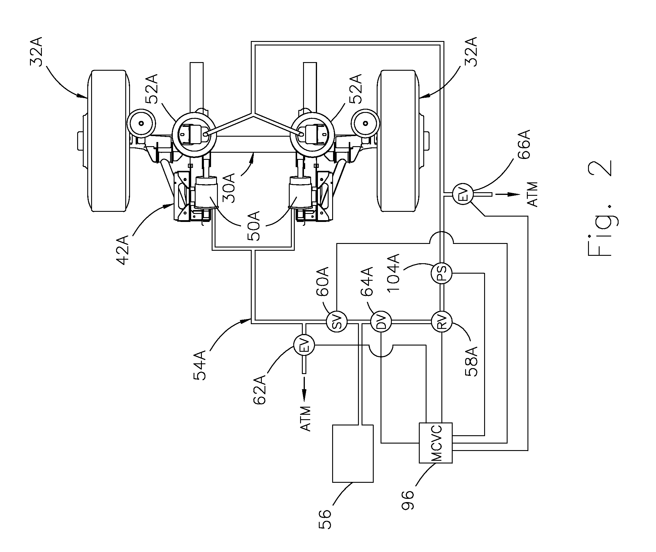
[0036]Referring to FIGS. 1-19, the present invention is disclosed as applied to a load-transporting motor vehicle in the form of a dump truck 10 having a cab 12 that serves as a vehicle operator and passenger compartment and a tiltable dump body 14 that serves as a load container and has a tail gate 16 for releasing a load when the dump body is tilted. With the cab and tiltable dump body mounted on a chassis 18 and the chassis in turn supported on a road surface 20 by both primary axles and deployable auxiliary axles. With the primary axles consisting of a forwardly-located axle 22 with steerable wheels 24 and rearwardly-located powered tandem axles 26A and 26B with dual wheels 28A and 28B respectively at their outboard ends. And with the auxiliary axles consisting of three pusher axles 30A, 30B and 30C with wheels 32A, 32B and 32C respectively, and a trailing axle 34 with wheels 36.

[0037]And to aid in understanding the important role that the axle load monitoring system according t...


PUM


Abstract

An axle load monitoring system is disclosed for a load-transporting motor vehicle having two or more primary axles and one or more auxiliary axles wherein the monitoring system detects a noncompliant axle carrying weight condition when the weight of the vehicle acting on any primary axle exceeds a prescribed maximum allowable axle carrying weight assigned to that axle and also when the weight acting on any group of the axles arranged consecutively exceeds a prescribed maximum allowable axle group carrying weight assigned to that axle group. And on such detection, the monitoring system recommends auxiliary axle usage that would result in no maximum allowable axle carrying weight and maximum allowable axle group carrying weight being exceeded provided the current gross vehicle weight does not exceed a prescribed maximum allowable gross vehicle weight determined by all of the axles and the current center of gravity of the vehicle is located within a certain compliance-manageable range. And with the monitoring system also recommending optimal auxiliary axle usage in other situations where full compliance may not be possible for various reasons.

Description

TECHNICAL FIELD[0001]This invention relates to axle load monitoring systems and more particularly to axle loading monitoring and auxiliary axle usage with respect to load-transporting motor vehicles having one or more auxiliary axles and is related to US Patent Application No. (Attorney Docket No. 1090A) entitled (DUAL TRAILING AXLE SUSPENSION SYSTEM″, US Patent Application No. (Attorney Docket No. 1090B) entitled “TRAILER HITCH”, and US Patent Application No. (Attorney Docket No. 1091) entitled “AUTOMATIC AUXILIARY AXLE CONTROL SYSTEM”.BACKGROUND OF THE INVENTION[0002]Load-transporting motor vehicles such as dump trucks, refuse trucks, transit concrete mixing trucks, open-bed trucks, utility trucks, military trucks and other vehicles of various types to which a significant load may be added for transport are limited in their load transporting ability by various factors. Such as the weight bearing capacity of their supporting axles and applicable federal and state law. With such law...

Claims


Application Information

Patent Timeline
IPC IPC(8): G01G19/08
CPCG01G19/08B60G2400/60B60G2204/11B60G17/017B60G2204/47B60G2300/36B60G2400/63
Inventor STRONG, BROOKSFISHER, JOSHUA CAYNE
Owner STRONG BROOKS
Learn More