
Hybrid vehicle control device

Active Publication Date: 2017-01-19
NISSAN MOTOR CO LTD
View PDF3 Cites 8 Cited by
  • Summary
  • Abstract
  • Description
  • Claims
  • Application Information

AI Technical Summary

Benefits of technology

[0012]Therefore, even when the vehicle is switched to a mode in which the engine is used to travel on an uphill road while in the electric vehicle mode, since the transmission ratio of the continuously variable trans

Problems solved by technology

That is, in the prior art described above, a transmission ratio control of the continuously variable transmission is not at all carried out during the EV mode; therefore, if the vehicle is stopped with a High-side transmission ratio, it is difficult to ensure the starting performance.
For example, when stopping the vehicle on an uphill road

Method used


Image

  • Hybrid vehicle control device
  • Hybrid vehicle control device
  • Hybrid vehicle control device

Examples


Example

First Embodiment

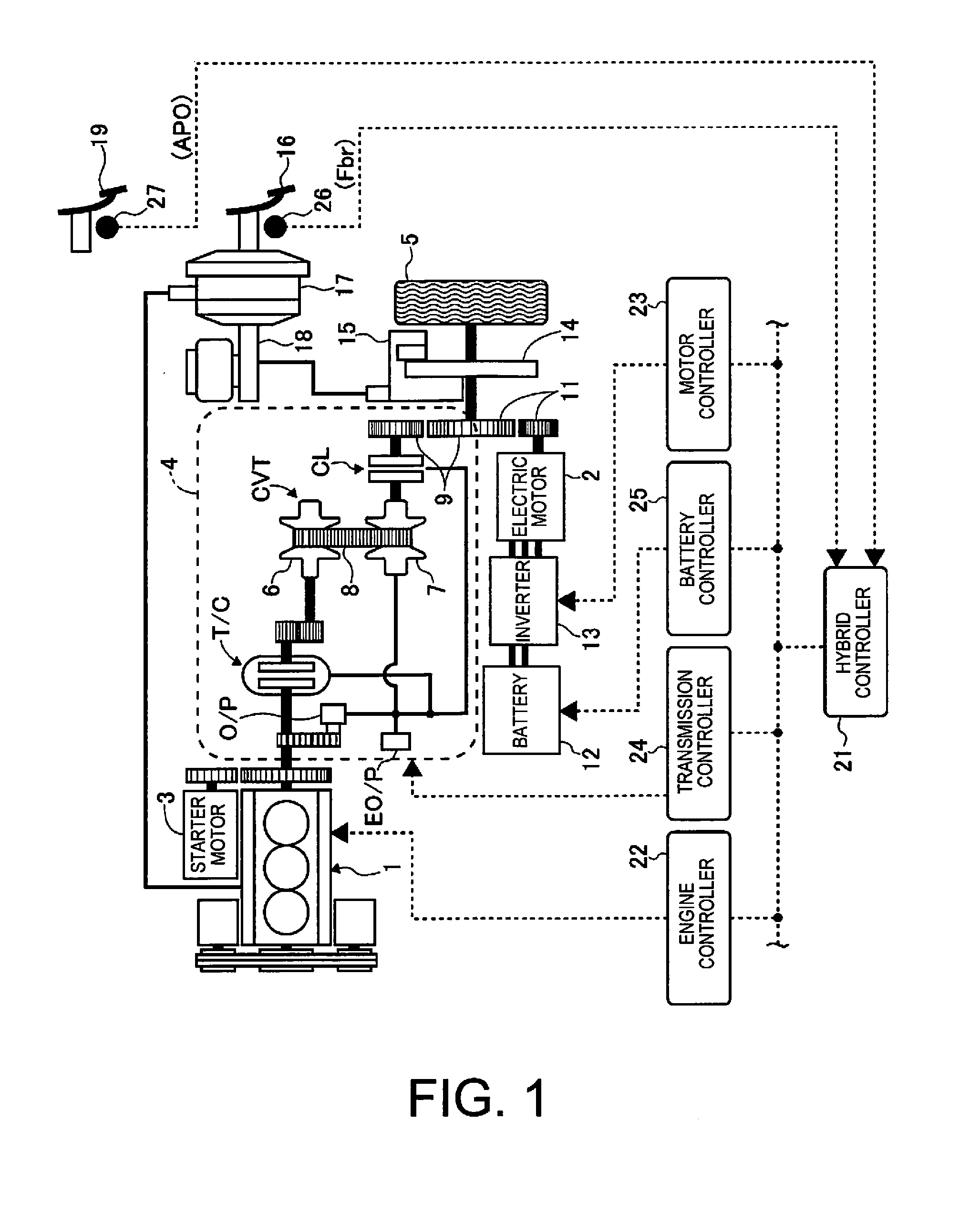
[0021]FIG. 1 is a schematic system view illustrating the drive system of the hybrid vehicle and the overall control system thereof of the first embodiment. The hybrid vehicle of FIG. 1 is equipped with an engine 1 and an electric motor 2 as power sources, and the engine 1 is started by a starter motor 3. The engine 1 is drivably coupled to a drive wheel 5 so as to be appropriately detachable via a V-belt type continuously variable transmission 4.

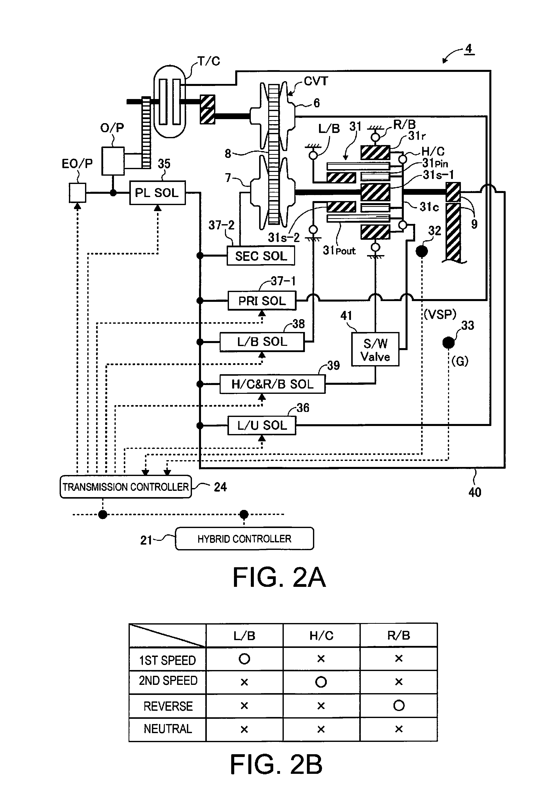
[0022]The variator CVT of the continuously variable transmission 4 is a V-belt type continuously variable transmission comprising a primary pulley 6, a secondary pulley 7, and a V-belt 8 (endless flexible member) that is bridged between these pulleys 6, 7. A configuration to bundle a plurality of elements by an endless belt was employed for the V-belt 8, but the configuration is not particularly limited thereto; for example, the chain method or the like may be employed. The primary pulley 6 is coupled to a crankshaft of the e...


PUM


Abstract

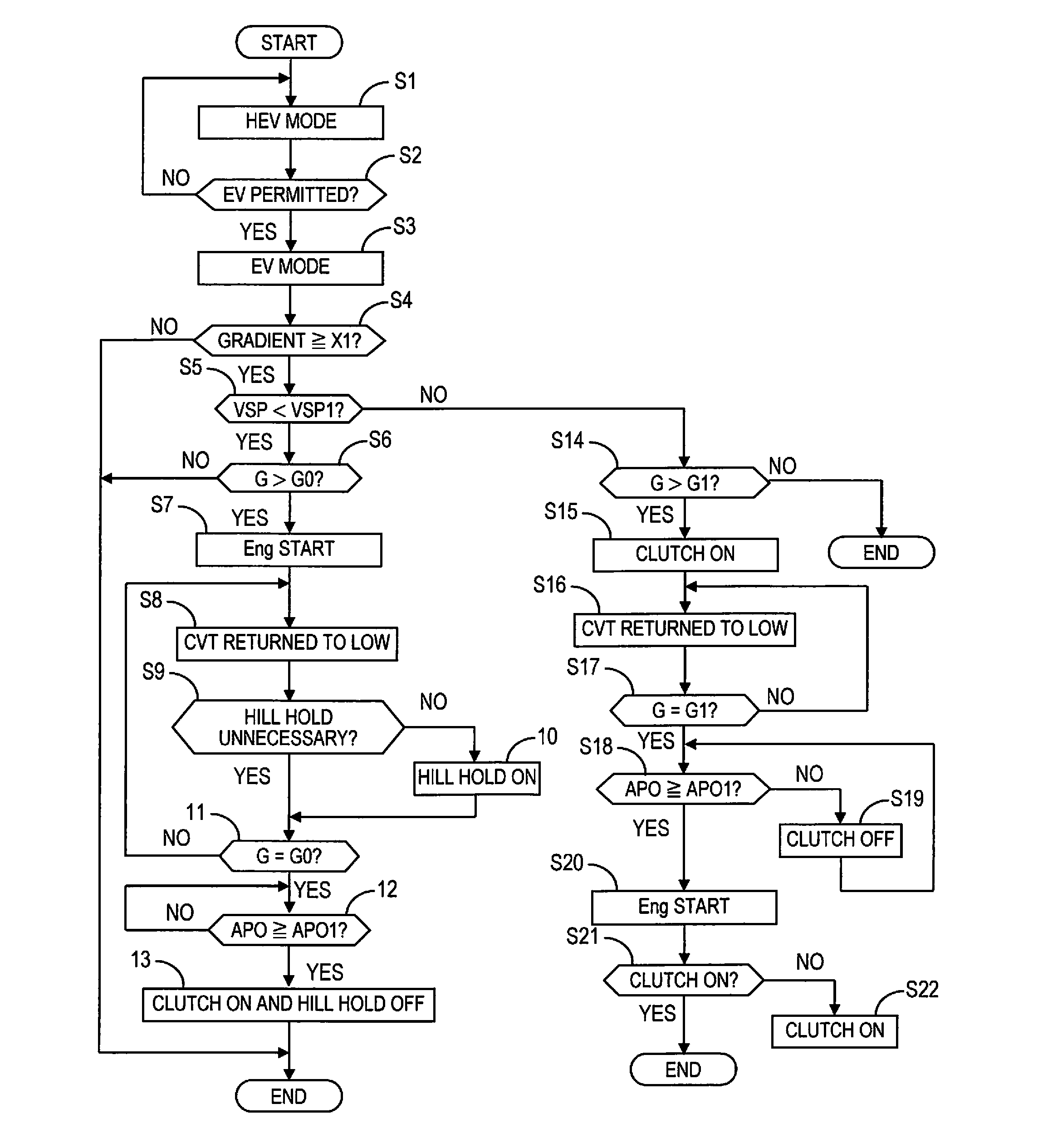
A hybrid vehicle control device is provided with at least one controller that controls the outputs of the engine and of the motor according to the driving state, the engagement and disengagement of the clutch, and the transmission ratio of the continuously variable transmission. The at least one controller is programmed to start the engine and forcibly downshift the continuously variable transmission to a transmission ratio with which it is possible to start on an uphill road upon determining that the vehicle is on an uphill road while in an electric vehicle mode in which it is possible to travel by the drive force of the motor with the clutch released and the engine stopped.

Description

CROSS-REFERENCE TO RELATED APPLICATIONS[0001]This application is a U.S. National stage application of International Application No. PCT / JP2015 / 052329, filed Jan. 28, 2015. This application claims right of priority based on Japanese Patent Application No. 2014-057584 filed to the Japan Patent Office on Mar. 20, 2014, and the disclosure of which is hereby entirely incorporated herein by reference.BACKGROUND[0002]Field of the Invention[0003]The present invention generally relates to a control device for a hybrid vehicle equipped with an engine and an electric motor as power sources, and that is capable of selecting between an electric travel mode (EV mode) for travel executed only by the electric motor and a hybrid travel mode (HEV mode) for travel executed by the electric motor and the engine.[0004]Background Information[0005]For example, a hybrid vehicle such as that disclosed in Japanese Laid-Open Patent Application No. 2000-199442 is known. In this hybrid vehicle, the engine is det...

Claims


Application Information

Patent Timeline
IPC IPC(8): B60W20/20B60W10/06B60W10/08B60K6/442B60W10/101B60K6/543B60K6/38B60W20/30B60W10/02
CPCB60W20/20B60Y2400/72B60W10/06B60W10/08B60W10/02B60W10/101B60K6/543B60K6/38B60K6/442B60W2550/142Y10S903/918Y10S903/912B60W2710/06B60W2710/1005B60Y2200/92B60Y2300/181B60Y2300/182B60Y2300/43B60Y2300/42B60Y2300/60B60Y2300/70B60W20/30B60K6/48B60W20/00B60W10/107B60W30/18027B60K2006/4808B60W2552/15Y02T10/62
Inventor YAMAMOTO, AKIHIRONAGAMINE, MORIHIROTAKANO, AKIRAOSHIO, SHINTAROKODAMA, YOSHIHISAHIRANO, TAKUROOTSUKA, YUKIFUMI
Owner NISSAN MOTOR CO LTD
Learn More