
Tool slide

Inactive Publication Date: 2017-01-19
VOESTALPINE GIESSEREI LINZ
View PDF8 Cites 1 Cited by
  • Summary
  • Abstract
  • Description
  • Claims
  • Application Information

AI Technical Summary

Benefits of technology

The invention is a prism guidance system that allows for easy separation of the slide body and slide bed, making maintenance or replacement of the guide body easier. The guide body is made of a removable blocking element at the end of the groove, which can be replaced in case of wear. The L-shaped sliding element can be composed of individual sliding elements or a single piece, but the latter increases installation effort. The separation of the prism guide body from the slide part allows for better matching of materials, making the guide body easier to install and remove.

Problems solved by technology

The wedge drives known from this prior art have disadvantages so that the slides used frequently have only a short service life and because of their structural design, are subject to intense wear.
They must therefore be frequently replaced even after short service lives because they are experiencing wear phenomena so that a precise conversion of vertical pressing forces is no longer possible, which results in unacceptable tolerances in metalworking.
In this wedge drive and also in the other known wedge drives in which the slide guide element and slide element are connected to each other by means of inclined strips and screws, it is disadvantageous that all of the tensile forces are introduced into the screws, as a result of which particularly at the moment in which an expansion of the screws and of the material surrounding them occurs, there is a negative impact on the clearance of the slide guide elements and slide elements that are moving relative to each other.
This subsequently results in a reduced service life since the wear in this region is particularly increased due to the distortion of the tool in this region.
It also turns out to be disadvantageous that the slide element cannot expand laterally when it is heated because it is restricted in this regard by the inclined strips.
This can likewise result in increased wear on the tool.
As a result of this, it is not necessary to provide a fastening to the slide guide element by means of screws, which are on the one hand susceptible to wear and on the other hand, can cause the above-mentioned negative impact on the clearance when they are heated.
In this case, it should be noted that the transmission of force and the guidance are not optimal.
In addition, this frequently requires more space and deformations can be observed due to the introduction of operating forces (working- and withdrawal forces).
With the known dovetail guidance, it is disadvantageous that the play must be frequently remachined, which requires the slide to be completely dismantled.
Furthermore, in all other sliders, installation and removal are very complex and labor-intensive.
On the one hand, this can only be carried out toward the rear in the whole slide body; particularly in large sliders due to the high weight of the slide body and the extremely limited installation spaces, large masses must be moved in narrow guidance with the aid of a crane.
With bracket slides, space to the side must be provided for the installation and removal so that for certain applications, there is no reliable guarantee that an optimized position of the slide will be achieved.
In the known tool slides, it is disadvantageous that the installation and removal are very complex and time-consuming.
On the one hand, slides of this kind can only be installed toward the rear in the whole slide body; particularly in large slides, this is difficult due to the weight of the slide body since very large masses must be moved in narrow guidance with the aid of a crane.
In addition, the most common tool slides, namely slides with bracket guidance, require a significant amount of space for installation and removal.

Method used


Image

  • Tool slide
  • Tool slide
  • Tool slide

Examples


Embodiment Construction

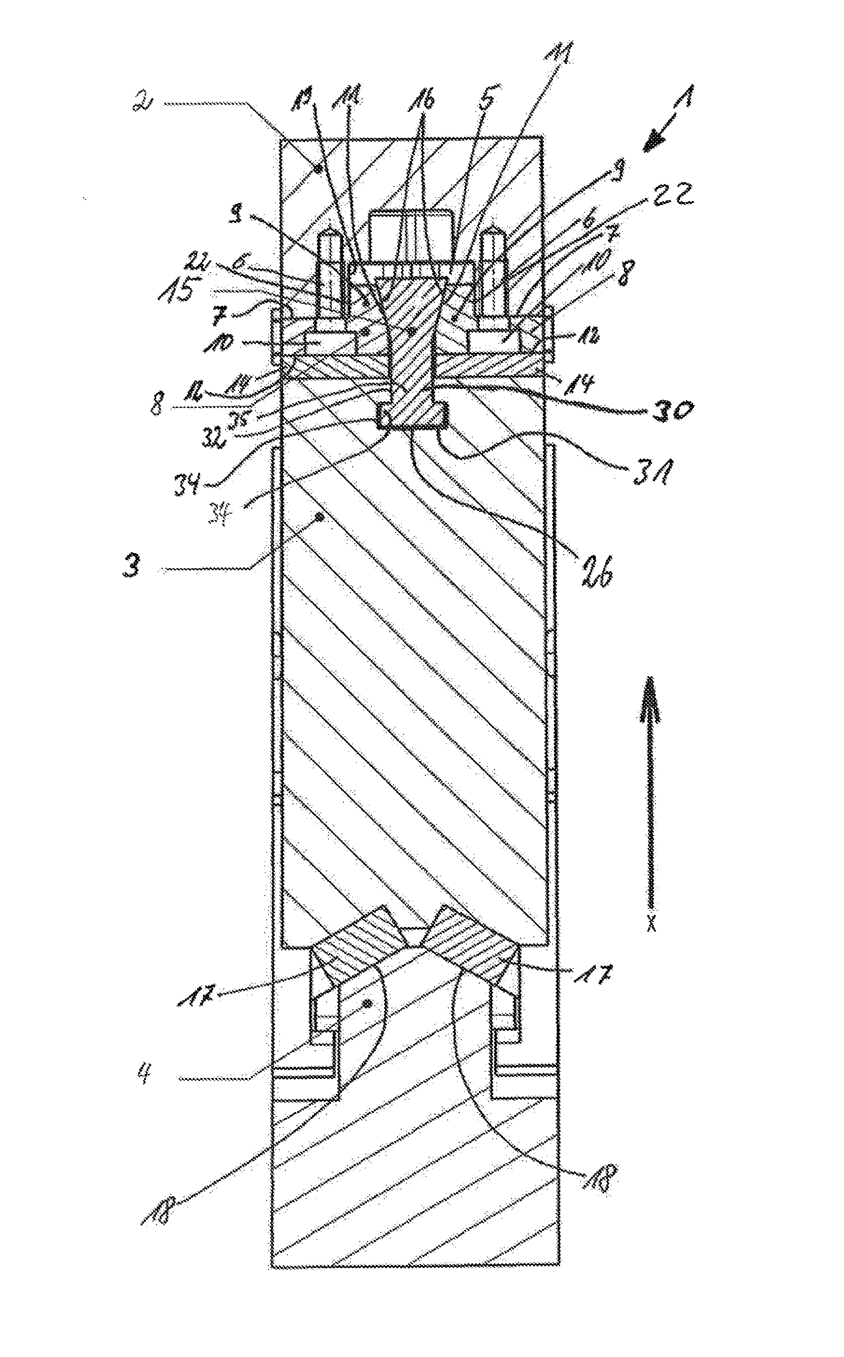
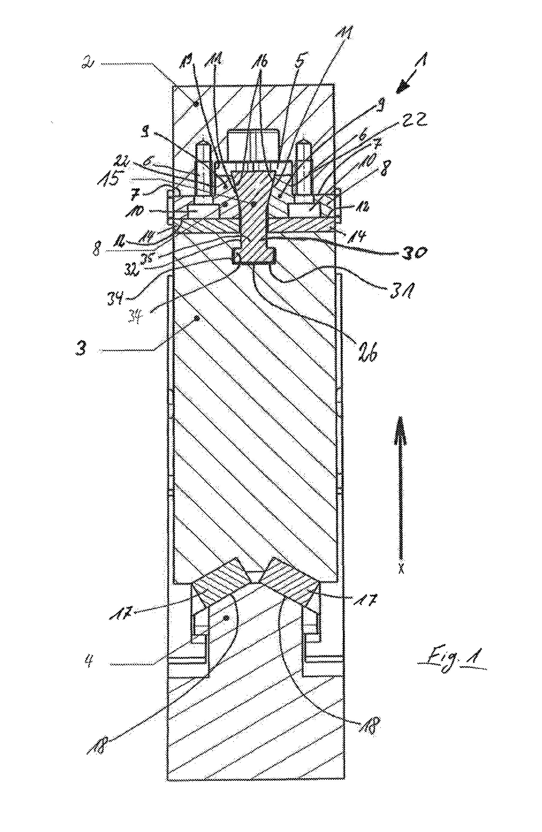
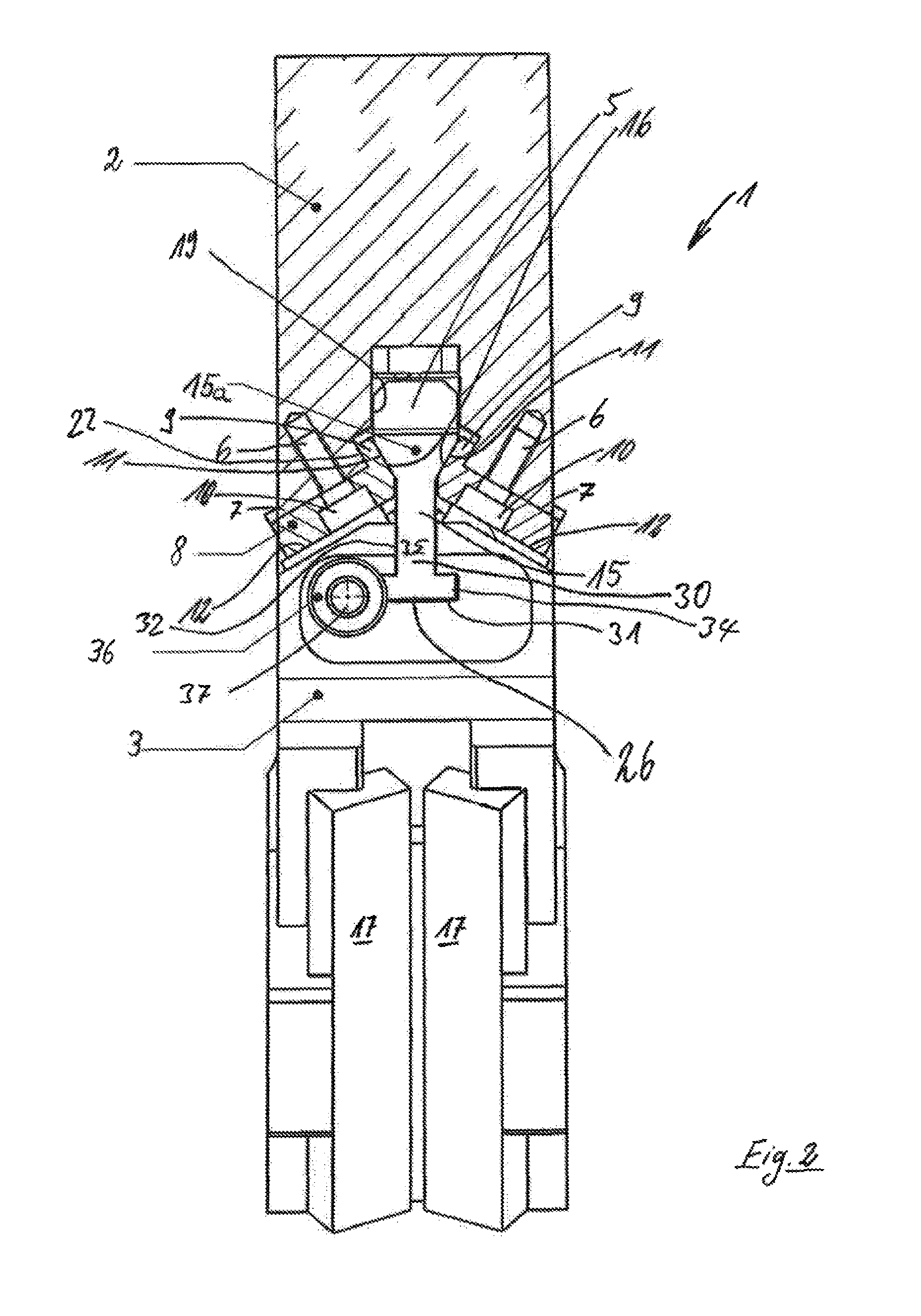
[0060]A tool slide 1 according to the invention has a slide bed 2, a slide body 3, and a driver 41.

[0061]In the case shown, the slide part 3 is arranged so that it is suspended on the slide bed 2; the slide part 3 can be lifted up from the driver 4. The driver 4 is usually positioned on a first tool half (the lower one in the case shown), while the slide part 3 is positioned above the slide bed 2 on a corresponding second (upper) tool half (not shown).

[0062]The slide bed 2 is embodied as approximately box-shaped and has an elongated rectangular groove 3; next to the elongated rectangular groove 5, screw holes 6 are provided to accommodate corresponding screws (not shown). The groove and the adjacent surfaces 7 delimiting the groove form a hearing surface for L-shaped slide strips 8, which rest on the surfaces 7 and extend into the groove with one L-leg 9. The L-shaped slide strips 8 have mounting holes 10 for screwing in mounting screws for insertion into screw holes 6. The L-shaped...


PUM

PropertyMeasurementUnit
Forceaaaaaaaaaa
Angleaaaaaaaaaa
Widthaaaaaaaaaa

Abstract

A tool slide, having at least one slide bed and one slide body. The slide body is axially movable in a restricted guiding fashion on the slide bed. A groove is provided in the slide body or in the slide bed and as a corresponding means, a guide body of the slide body or slide bed is supported in an axially movable, guiding fashion in the groove. The guide body is embodied as rail-like or slat-like and is positioned with part of its width inserted in a secured fashion into a groove in the slide body or slide bed.

Description

FIELD OF THE INVENTION[0001]The invention relates to a tool slide.BACKGROUND OF THE INVENTION[0002]Tool slides, which are also referred to as wedge drives, are known.[0003]Wedge drives are used in tools in metalworking, e.g. in forming presses. These wedge drives are usually connected to devices or tools that make it possible to perform a punching procedure or some other deforming procedure. A conventional wedge drive has an upper guide part, which includes a slide element and a slide guide element, and a lower guide part, which includes a driver element, or vice versa. On the slide guide element side, the wedge drives are moved by means of a drive that exerts a generally vertical pressing force. On the driver element side, wedge drives in the tool or press are fastened to a base plate onto which the workpiece to be machined is placed directly or by means of a corresponding support device.[0004]DE 26 40 318 B2 has disclosed a wedge drive for converting a vertical pressing force into...

Claims


Application Information

Patent Timeline
IPC IPC(8): B21D28/32B30B15/02B21D37/14
CPCB21D28/32B30B15/026B21D37/14B21D28/325B30B1/40
Inventor MEYER, MARKUS
Owner VOESTALPINE GIESSEREI LINZ
Learn More