Condensed cyclic compound and organic light-emitting device including the same
- Summary
- Abstract
- Description
- Claims
- Application Information
AI Technical Summary
Benefits of technology
Problems solved by technology
Method used
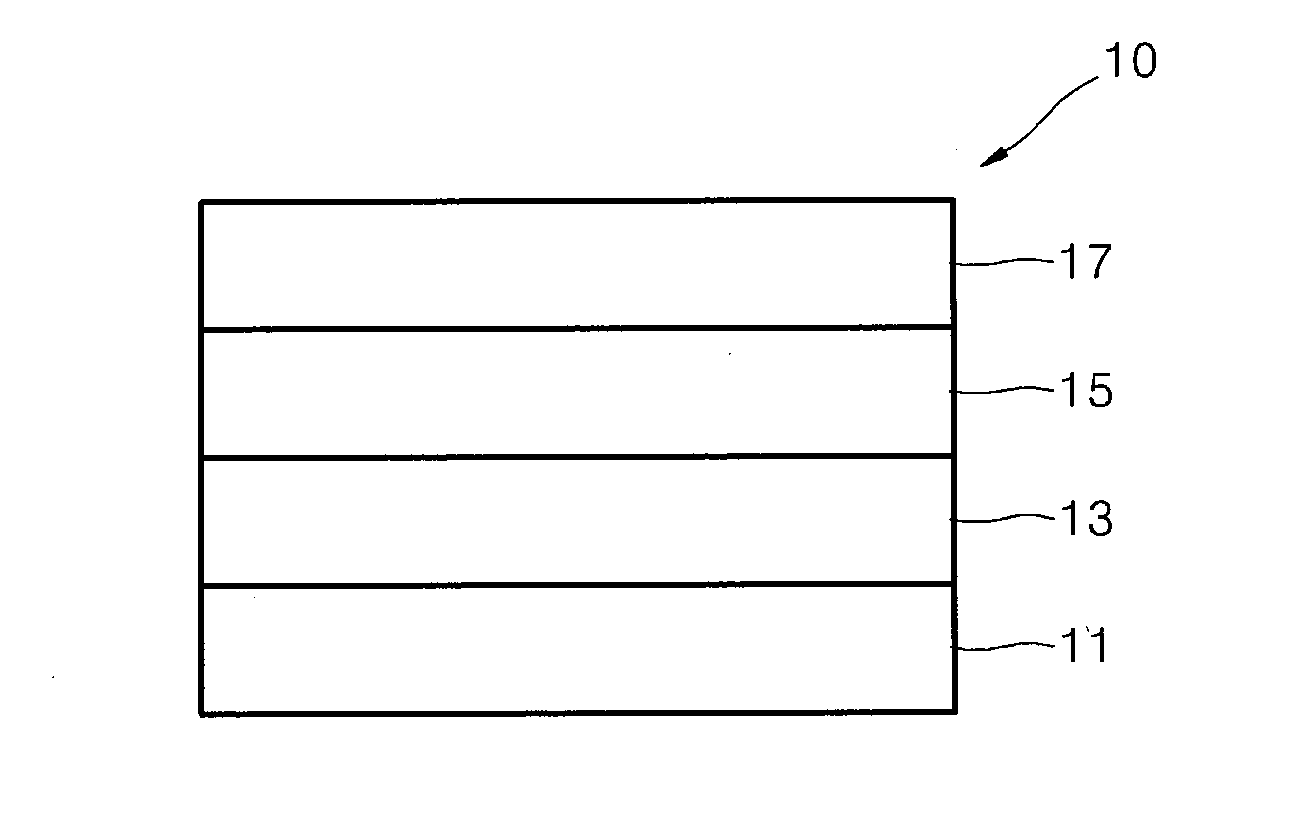
Image


Examples
synthesis example 1
Synthesis of Compound 1
[0158]
Synthesis of Intermediate I-2
[0159]39.39 g (120.0 mmol) of Intermediate I-1, 10.38 g (60.0 mmol) of 2-amino-4-bromopyridine, 3.47 g (3.0 mmol) of Pd(PPh3)4, and 24.84 g (180.0 mmol) of K2CO3 were dissolved in 75 mL of a THF / H2O mixed solution (a volumetric ratio of 2 / 1), and then, at a temperature of 70° C., the resultant solution was stirred for 5 hours. The reaction solution was cooled to room temperature, and then extracted three times with 100 mL of water and 100 mL of diethylether. A collected organic layer was dried by using (utilizing) magnesium sulfate, and then, the residual obtained by evaporating the solvent therefrom was separation-purified by silica gel column chromatography to obtain 18.84 g (yield of 80%) of Intermediate I-2. The obtained compound was identified by LC-MS. (C21H14N2: calc. 294.36, obtained 294.12)
Synthesis of Intermediate I-3
[0160]22.08 g (75 mmol) of Intermediate I-2 was mixed with 9.6 mL (48%) of a hydrobromic acid (HBr),...
synthesis example 2
Synthesis of Compound 2 (i.e., Compound B)
[0165]
[0166]Intermediate II-2 was synthesized in the same manner as used (utilized) to synthesize Intermediate I-2, except that 6-bromo-4-aminopyrimidine was used (utilized) instead of 2-amino-4-bromopyridine.
[0167]Compound 2 (i.e., Compound B) was obtained in the same manner as used (utilized) to synthesize Compound 1, except that Intermediate II-2 was used (utilized) instead of Intermediate I-2, and Intermediate II-8 was used (utilized) instead of Intermediate I-8. (C41H23N3: calc. 557.66, obtained 557.19)
synthesis example 3
Synthesis of Compound 3 (i.e., Compound C)
[0168]
Synthesis of Intermediate III-2
[0169]19.69 g (60.0 mmol) of Intermediate III-1, 13.56 g (60.0 mmol) of 2,4-dichloro-6-phenyl-1,3,5-triazine, 1.73 g (1.5 mmol) of Pd(PPh3)4, and 12.44 g (90.0 mmol) of K2CO3 were dissolved in 75 mL of a THF / H2O mixed solution (a volumetric ratio of 2 / 1), and then, at a temperature of 70° C., the resultant solution was stirred for 5 hours. The reaction solution was cooled to room temperature, and then extracted three times with 100 mL of water and 100 mL of diethylether. A collected organic layer was dried by using (utilizing) magnesium sulfate, and then, the residual obtained by evaporating the solvent therefrom was separation-purified by silica gel column chromatography to obtain 23.51 g (yield of 50%) of Intermediate III-2. The obtained compound was identified by LC-MS. (C21H14N2: calc. 391.86, obtained 391.09)
Synthesis of Compound 3 (i.e., Compound C)
[0170]19.59 g (50.0 mmol) of Intermediate III-2, 16...
PUM
 Abstract
Description
Claims
Application Information
 - R&D
- Intellectual Property
- Life Sciences
- Materials
- Tech Scout
- Unparalleled Data Quality
- Higher Quality Content
- 60% Fewer Hallucinations
Browse by: Latest US Patents, China's latest patents, Technical Efficacy Thesaurus, Application Domain, Technology Topic, Popular Technical Reports.
© 2025 PatSnap. All rights reserved.Legal|Privacy policy|Modern Slavery Act Transparency Statement|Sitemap|About US| Contact US: help@patsnap.com