
A flexible display apparatus and an encapsulation method thereof

Inactive Publication Date: 2017-01-12
BOE TECH GRP CO LTD
View PDF4 Cites 11 Cited by
  • Summary
  • Abstract
  • Description
  • Claims
  • Application Information

AI Technical Summary

Benefits of technology

The disclosure provides a flexible display apparatus with an improved resistance to bending and cracks. This is achieved through a protective layer that has multiple functions. When the display is bent, the protective layer acts to buffer the stress caused by bending, reducing the likelihood of developing micro-cracks. Additionally, the protective layer blocks the expansion of the cracks, making it more difficult to produce. An encapsulation method is also provided, which involves forming a protective layer over the cathode of an OLED device. The protective layer has a multi-functional region that acts as a water oxygen barrier and stress blocker. The thickness of the film layer in the multi-functional region is thinner than that of the film layer in the water oxygen barrier region, and / or the film texture in the multi-functional region is looser than that in the water oxygen barrier region. This method ensures that the pathways for cracks to expand are cut off, improving the flex resistance of the flexible display apparatus.

Problems solved by technology

The inventors have studied deeply the problem with the encapsulation of the flexible display device in the prior art, and found the cause for the appearance of the above-mentioned problem: when the flexible display device is bent, the encapsulating film layer is easily caused to crack along the defect locations, owing to small holes present in the encapsulating film layer and the problem with the stress matching between the encapsulating film layer and a film layer it contacts with.
The above-mentioned defect locations refer to the pinholes of the film layer produced at the time of coating, or the micro-cracks due to a poor stress between the film layers, and when the flexible display device is bent, these locations are the points of stress concentration, and are easily affected by an external force to crack.
Since the protective layer in the flexible display apparatus according to the disclosure comprises a multi-functional region, when the flexible display apparatus is bent, the stress of the film layer resulting from bending of the film layer gets buffered in the multi-functional region, that is, the existence of the multi-functional region may cut off the expansion path of the stress of the film layer, and thereby may reduce the possibility of producing micro-cracks at the time of bending; meanwhile, the existence of the multi-functional region may further block the expansion of the cracks.

Method used


Image

  • A flexible display apparatus and an encapsulation method thereof
  • A flexible display apparatus and an encapsulation method thereof
  • A flexible display apparatus and an encapsulation method thereof

Examples


first embodiment

[0031]FIG. 3 shows a schematic diagram of the encapsulation of a flexible display apparatus according to the disclosure, wherein the protective layer corresponds to the first way of construction in the above. As shown in FIG. 3, on a substrate 10 is a flexible substrate 11, on the flexible substrate 11 are arranged an OLED device 12 and a circuit driving the OLED device 12, thereon is arranged a protective layer for encapsulation, and on the protective layer is arranged a protective film 14, which protective film 14 is mainly used for preventing the protective layer from being scratched. As shown in the figure, the protective layer comprises a first protective layer 131 which is continuously distributed and a second protective layer 132 which is patterned, wherein the first protective layer 131 completely covers a cathode of the OLED device 12 to prevent the immersion of water and oxygen, and the second protective layer 132 is only distributed in a corresponding area over a pixel.

[0...

second embodiment

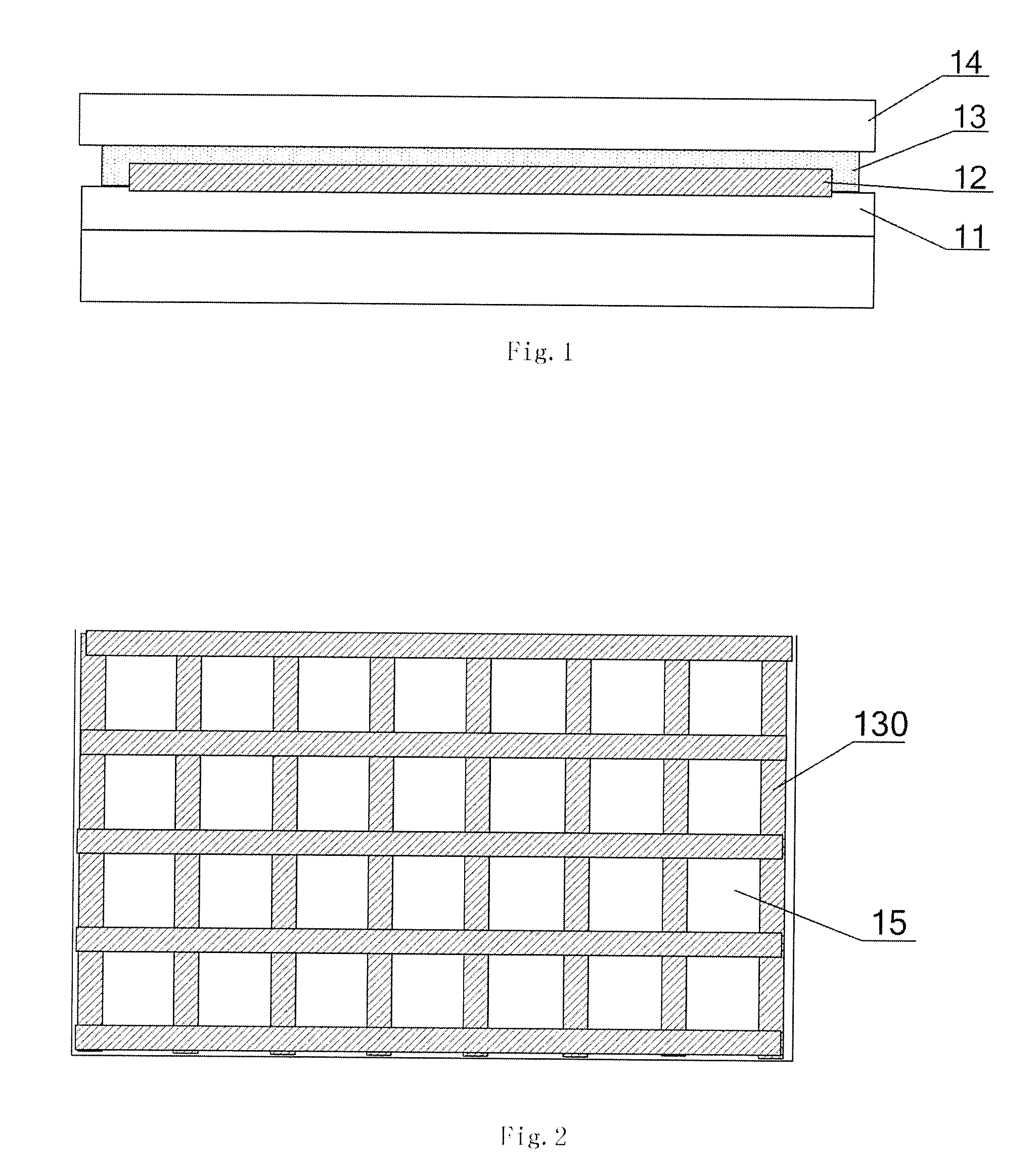
[0036]FIG. 4 shows a schematic diagram of the encapsulation of a flexible display apparatus according to the disclosure, wherein the protective layer corresponds to the second way of construction in the above. The differences between the encapsulation structure of FIG. 4 and that of FIG. 3 lie in that in FIG. 4, the protective layer comprises: a first film layer 134 with a dense film texture distributed in a corresponding area over a pixel, i.e., a water oxygen barrier region 120; and a second film layer 135 with a loose film texture distributed in a gap between the first film layers 134 or in an area corresponding to a spacing between adjacent pixels, i.e., a multi-functional region 130. It needs to be noted that in FIG. 4, the water oxygen barrier region 120 and the multi-functional region 130 only relate to the partition of the protective layer (comprising the first film layer 134 and the second film layer 135), but are not related with other devices (like the protective film 14,...


PUM


Abstract

The disclosure describes a flexible display apparatus and an encapsulation method thereof, which are capable of solving the problem of easily producing cracks with the existing encapsulating film layer and improving the performance of flex resistance of the flexible display apparatus. The flexible display apparatus according to the disclosure comprises: an LED device, and a protective layer arranged on a cathode of the OLED device, wherein the protective layer comprises a water oxygen barrier region and a multi-functional region, the multi-functional region has dual functions of a water oxygen barrier and stress blocking, and the thickness of the film layer in the multi-functional region is less than that of the film layer in the water oxygen barrier region, and / or the film texture in the multi-functional region is looser than that in the water oxygen barrier region.

Description

FIELD OF THE INVENTION[0001]The disclosure relates to the field of display, and in particular, to a flexible display apparatus and an encapsulation method thereof.BACKGROUND OF THE INVENTION[0002]The development of traditional flat panel display device technologies has become increasingly mature, whereas flexible display devices are about to become the mainstream in the display field by virtue of their characteristics of being light & thin, bendable, and impact resistant. Therein, OLEDs (Organic Light Emitting Diodes) have become one of the hot spots researched in the field of flexible display recently due to having the excellent performances of a rapid response speed, a wide viewing angle, high luminance, low power consumption, being self-luminous, and flex resistance, etc.[0003]An OLED device is very sensitive to water vapor and oxygen, and it is prone to decay. An effective encapsulation may prevent immersion of the water vapor and oxygen, prevent the organic materials from agein...

Claims


Application Information

Patent Timeline
IPC IPC(8): H01L51/52H01L51/56H01L51/00
CPCH01L51/5253H01L51/0097H01L27/326H01L51/56H01L51/5237H10K59/121H10K50/844Y02E10/549E21B33/12E21B43/11E21B43/112E21B43/14E21B7/00E21B23/001H10K77/111H10K2102/311H10K50/84H10K71/00E21B4/04E21B31/002
Inventor SUN, TAOZHOU, WEIFENGGAO, JING
Owner BOE TECH GRP CO LTD
Learn More