
Methods and systems for three-dimensional visualization of deviation of volumetric structures with colored surface structures

Active Publication Date: 2017-01-12
SIEMENS HEALTHINEERS INT AG
View PDF7 Cites 6 Cited by
  • Summary
  • Abstract
  • Description
  • Claims
  • Application Information

AI Technical Summary

Benefits of technology

This patent is about a computer system that can convert multiple sets of data into a three-dimensional representation on a computer screen. The system can also compare different parts of the data and measure their distance from each other. The computer system uses a color assignment module to assign different colors to the different parts of the data. The "technical effect" is that it allows for easier comparison and analysis of data with three-dimensional structures. The methods, computer system, and computer program product described here can be used in any field where segmented structures of the source and target volumes are available.

Problems solved by technology

Technical challenges in combining hundreds of sectional images of CT scan to produce a three-dimensional (“3D”) image representation of a body organ have been hindered by some principal issues, such as conversion methodologies, surface color manipulation and insufficient image resolution.

Method used


Image

  • Methods and systems for three-dimensional visualization of deviation of volumetric structures with colored surface structures
  • Methods and systems for three-dimensional visualization of deviation of volumetric structures with colored surface structures
  • Methods and systems for three-dimensional visualization of deviation of volumetric structures with colored surface structures

Examples


first embodiment

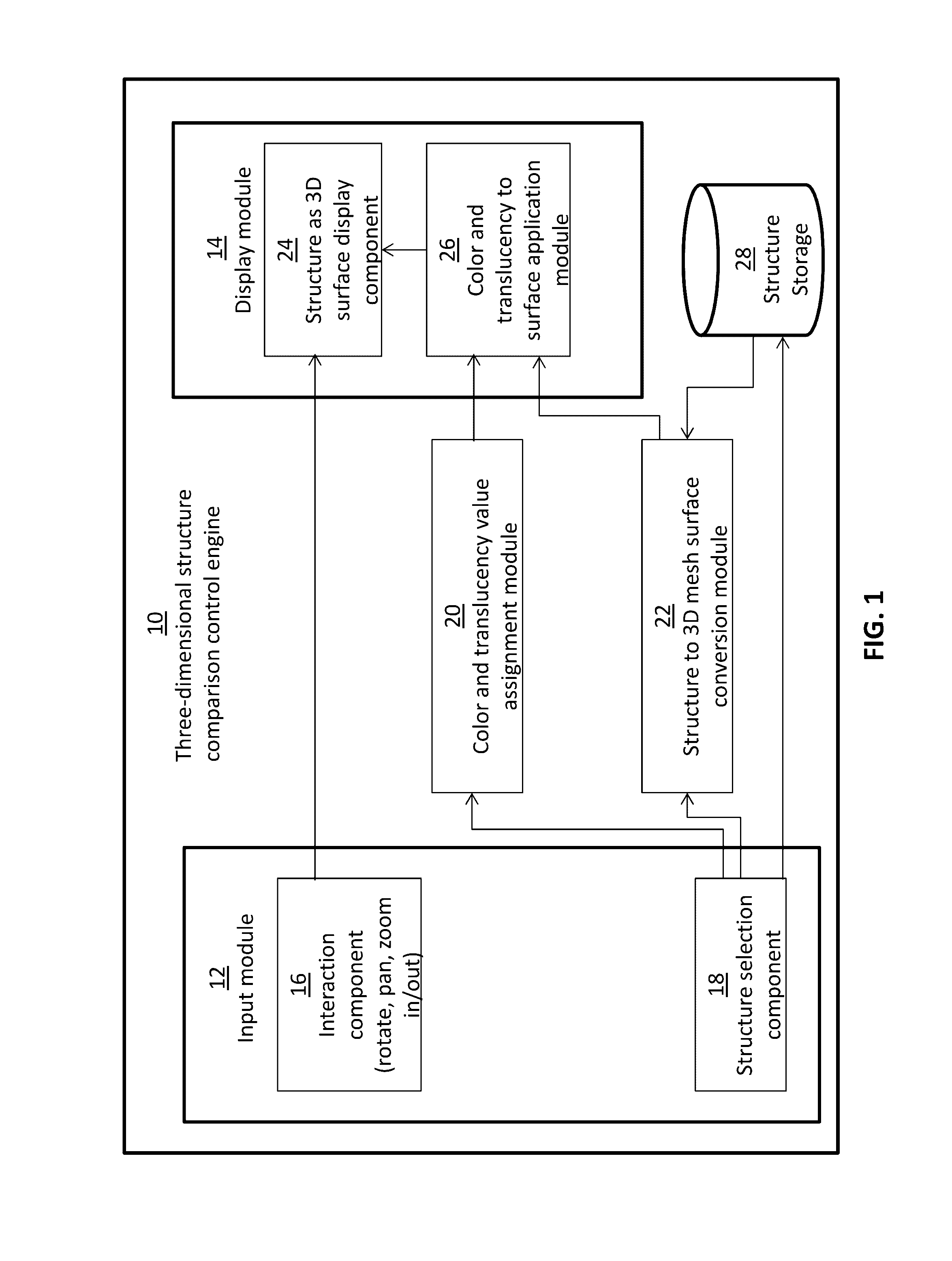
[0028]FIG. 1 is a software system diagram illustrating the three-dimensional structure comparison control engine 10 that comprises an input module 12 and a display module 14, both of which are communicatively coupled to a color and translucency assignment module 20 and a structure to three-dimensional mesh surface conversion module 22. A structure storage 28 is further bidirectionally coupled to a structure selection component 18 of the input module 12 and the structure to three-dimensional mesh surface conversion module 22. The input module 12 further includes an interaction component 16 for rotating, panning, zooming in and zooming out functions. The display module 14 includes a structure as three-dimensional surface display component 14, and a color and translucency to surface application module 26. The color and translucency value assignment module 20 in the three-dimensional structure comparison control engine 10 is configured to assign color and translucency value to one or mo...

second embodiment

[0041]FIG. 9 is a software system diagram illustrating the three-dimensional structure comparison control engine 176 that comprises an input module 12 and a display module 14, both of which are communicatively coupled to a distance field computation, color to vertex assignment, and shading module 178 and a structure to three-dimensional mesh surface conversion module 22. A structure storage 28 is further bidirectionally coupled to a structure selection component 18 of the input module 12 and the structure to three-dimensional mesh surface conversion module 22. The input module 12 further includes an interaction component 16 for rotating, panning, zooming in and zooming out functions. The display module 14 includes a structure as three-dimensional surface display component 14, and a shading application component 180. The distance field computation, color to vertex assignment and shading module 178 is configured to determine distance value, color to vertex value, and shading value of ...


PUM


Abstract

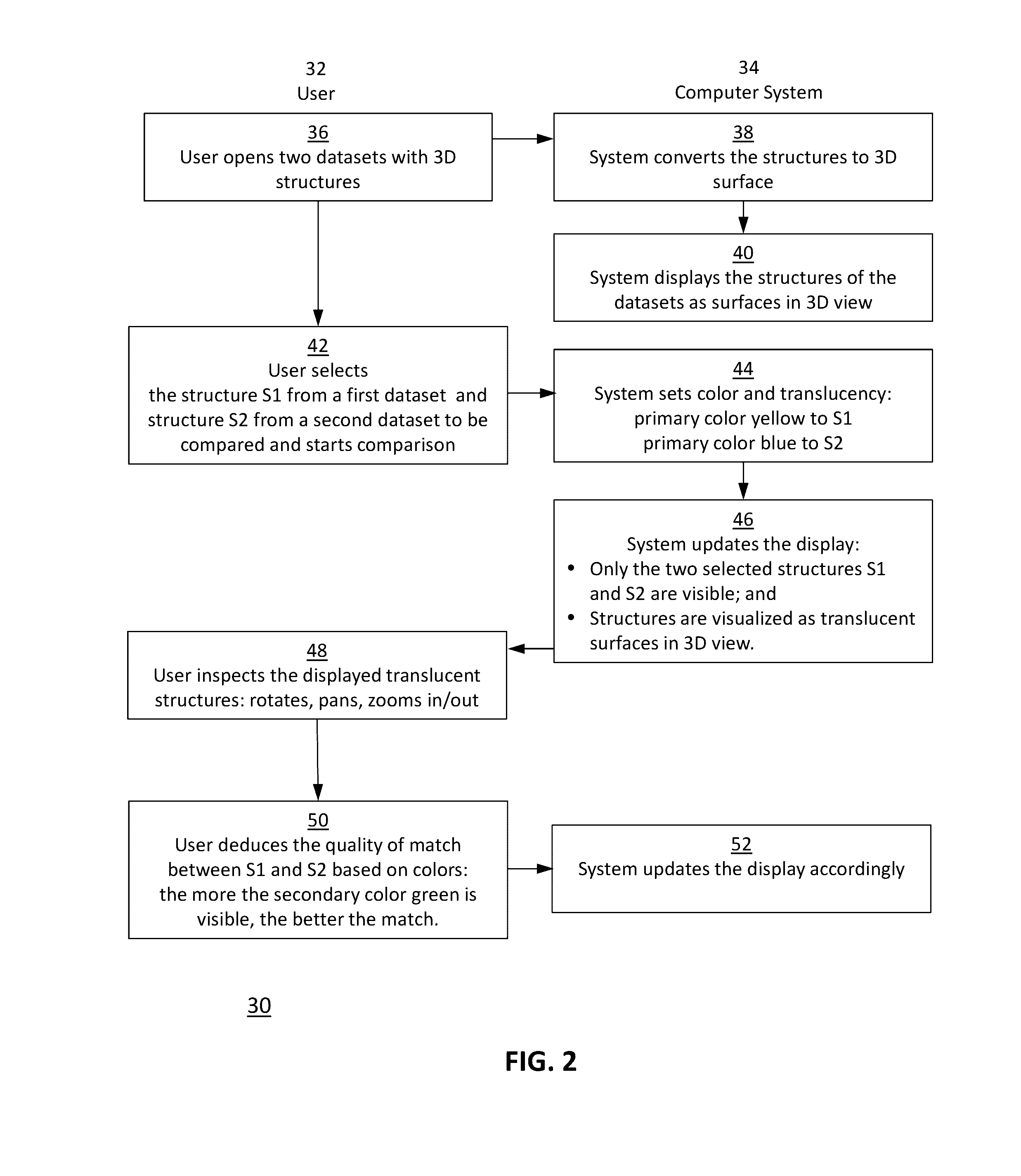
Embodiments of the present disclosure are directed to methods and computer systems for converting datasets into three-dimensional (“3D”) mesh surface visualization, displaying the mesh surface on a computer display, comparing two three-dimensional mesh surface structures by blending two primary different primary colors to create a secondary color, and computing the distance between two three-dimensional mesh surface structures converted from two closely-matched datasets. For qualitative analysis, the system includes a three-dimensional structure comparison control engine that is configured to convert dataset with three-dimensional structure into three-dimensional surfaces with mesh surface visualization. The control engine is also configured to assign color and translucency value to the three-dimensional surface for the user to do qualitative comparison analysis. For quantitative analysis, the control engine is configured to compute the distance field between two closely-matched datasets.

Description

TECHNICAL FIELD[0001]The present invention relates generally to the interdisciplinary fields of image data analysis and computer system, and more particularly to the dataset analysis and computer system for transforming datasets to three-dimensional mesh surface structure to display on a computer display and for computing the deviations between the structures to color code the quantified deviations on the computer display.BACKGROUND ART[0002]Three-dimensional imaging on a computer display has become more prevalent in recent years with the advancement of computing power and computer modeling. Active research and development in biological science and engineering have been ongoing for processing three-dimensional images for instructional purposes and medical applications. One area of particular interest stems from the medical imaging field for the treatments of patients to compare imaging scans of a patient taken before, during and after the treatments to assess the progress and effect...

Claims


Application Information

Patent Timeline
IPC IPC(8): G06T15/87G06T15/10G06T15/04G06T15/50G06T15/08
CPCG06T15/87G06T15/503G06T15/10G06T15/04G06T15/08
Inventor ZATONYI, JANOSNOVOTNI, MARCINKUNZ, PATRIK
Owner SIEMENS HEALTHINEERS INT AG
Learn More