
Liquid crystal display device

a display device and liquid crystal technology, applied in static indicating devices, instruments, non-linear optics, etc., can solve the problems of circuit lines being eroded, circuit lines may be eroded, and the inorganic layer formed of an organic material cannot be closely bonded to the inorganic layer on the lower substrate, so as to minimize moisture infiltration, improve reliability of liquid crystal display devices, and minimize damage

Active Publication Date: 2017-01-12
LG DISPLAY CO LTD
View PDF9 Cites 9 Cited by
  • Summary
  • Abstract
  • Description
  • Claims
  • Application Information

AI Technical Summary

Benefits of technology

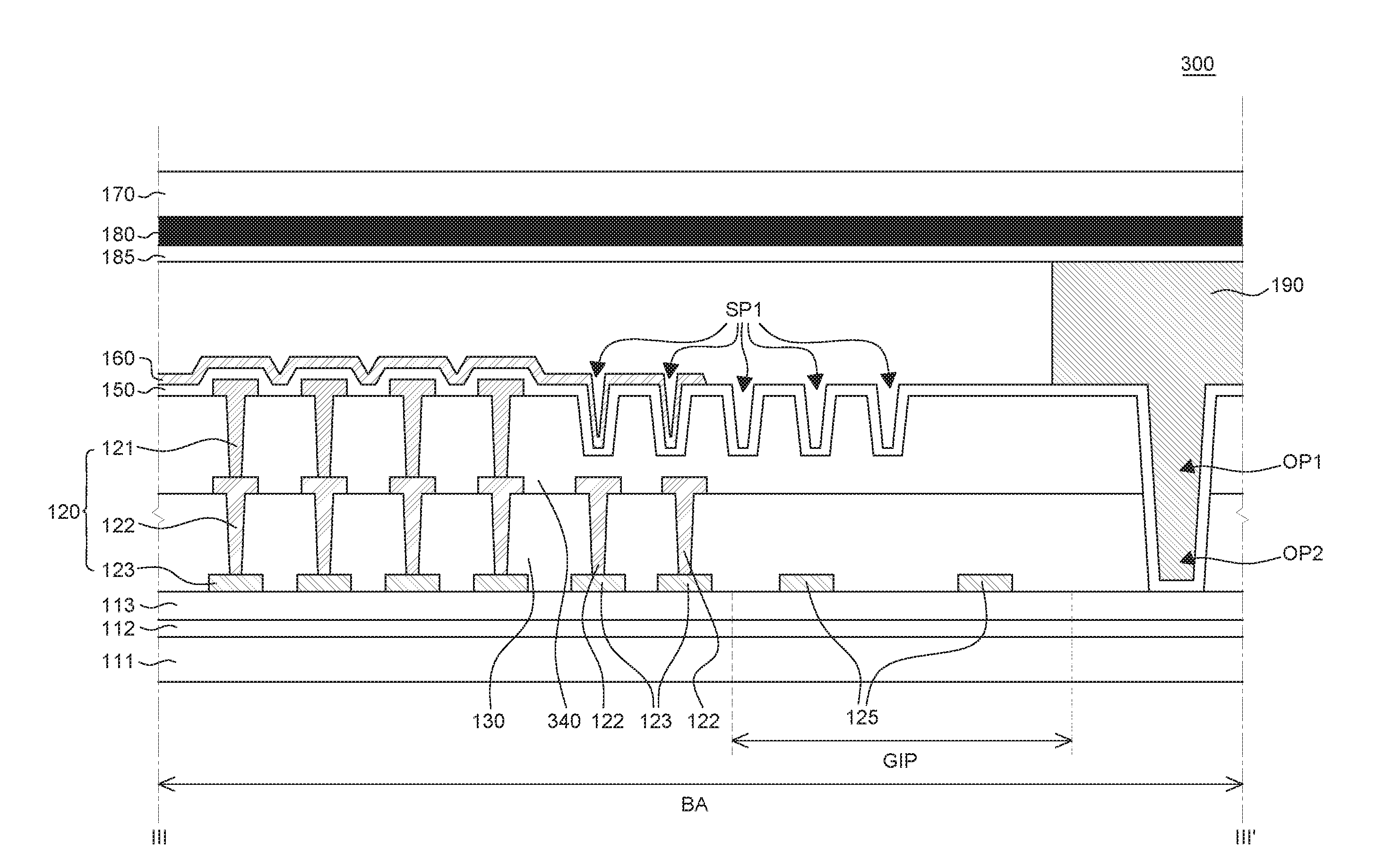
The present invention provides a liquid crystal display device wherein an inorganic insulation layer is placed in direct contact with an inorganic layer of a lower substrate to minimize moisture infiltration. This improves the reliability of the device and reduces damage to the driving circuit caused by moisture. Additionally, the invention maximizes the contact area between a sealant and the inorganic insulation layer through upper and lower openings, improves adhesion, and reduces the likelihood of a decrease in sealant adhesion caused by overlap between an alignment layer and the sealant. The invention also reduces resistance by connecting two metal lines, and allows for a small width of a touch line in the small bezel area. Overall, this invention improves the performance and reliability of the liquid crystal display device.

Problems solved by technology

However, the insulation layer formed of an organic material cannot be closely bonded to the inorganic layer on the lower substrate.
Upon infiltration of moisture, circuit lines in the driving circuit may be eroded by the moisture.
For example, if a voltage is applied to the circuit lines as being exposed to the moisture, the circuit lines may be eroded by an electric field and the moisture.
Therefore, the erosion of the driving circuit may be accelerated, and, thus, the reliability of the LCD device may deteriorate.
Therefore, a touch signal may be delayed.

Method used


Image

  • Liquid crystal display device
  • Liquid crystal display device
  • Liquid crystal display device

Examples


Embodiment Construction

[0028]Advantages and features of the present disclosure, and methods for accomplishing the same will be more clearly understood from exemplary embodiments described below with reference to the accompanying drawings. However, the present disclosure is not limited to the following exemplary embodiments but may be implemented in various different forms. The exemplary embodiments are provided only to complete disclosure of the present disclosure and to fully provide a person having ordinary skill in the art to which the present disclosure pertains with the category of the disclosure, and the present disclosure will be defined by the appended claims.

[0029]The shapes, sizes, ratios, angles, numbers, and the like illustrated in the accompanying drawings for describing the exemplary embodiments of the present disclosure are merely examples, and the present disclosure is not limited thereto. Like reference numerals generally denote like elements throughout the present specification. Further,...


PUM


Abstract

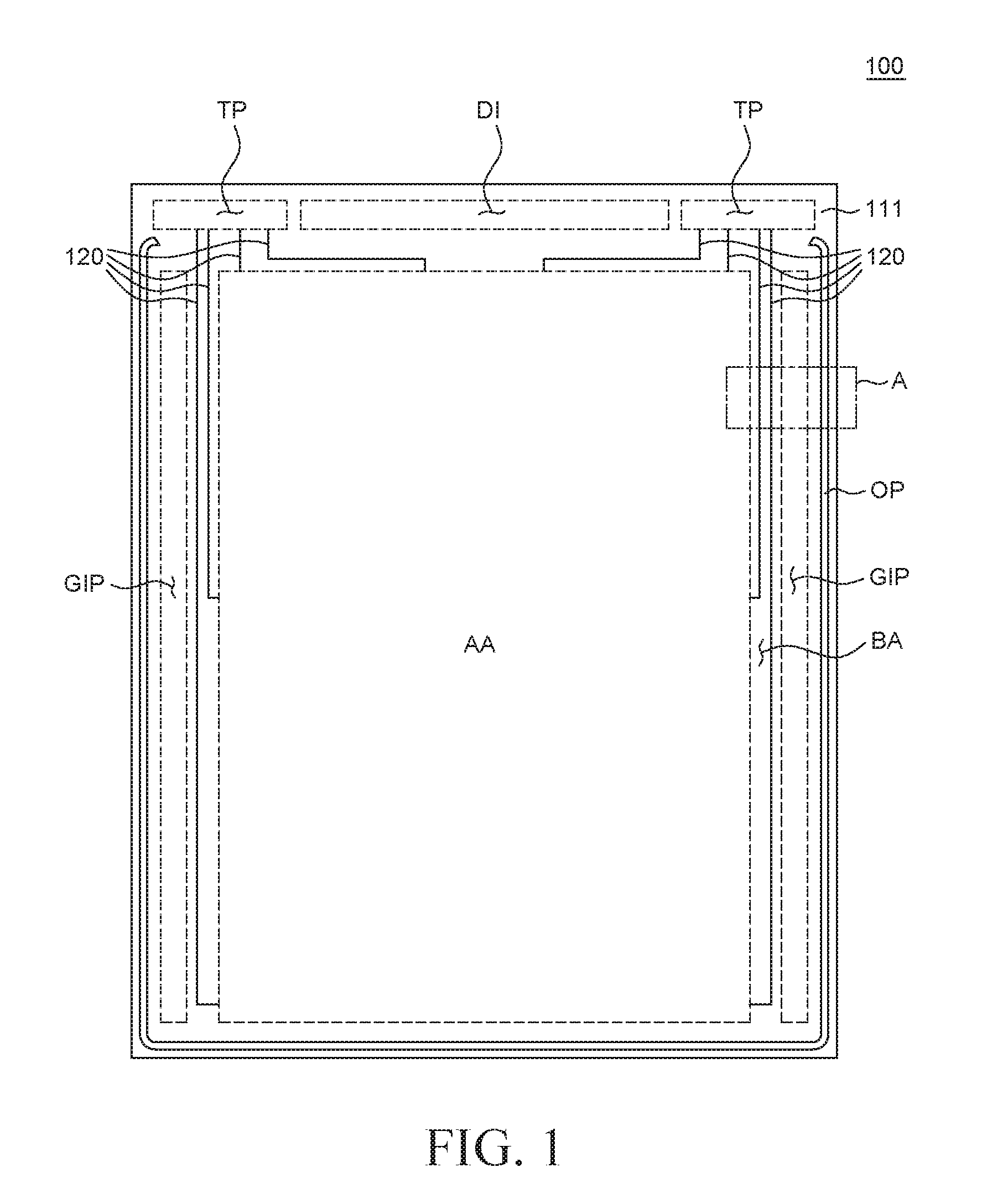
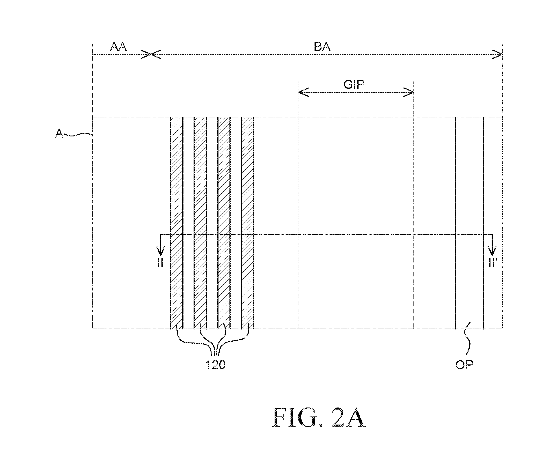
A liquid crystal display device is provided. The liquid crystal display device includes a driving circuit; a lower insulation layer; an upper insulation layer; and an inorganic insulation layer. The driving circuit is disposed in a bezel area on a lower substrate. The lower insulation layer includes a lower opening through which an inorganic layer on the lower substrate is exposed and the lower opening is located at an outer side of the lower substrate than the driving circuit. The upper insulation layer is disposed on the lower insulation layer and includes an upper opening corresponding to the lower opening. The inorganic insulation layer is disposed on the upper insulation layer and in direct contact with the inorganic layer on the lower substrate so as to minimize damage to the driving circuit caused by infiltration of moisture from the outside.

Description

CROSS-REFERENCE TO RELATED APPLICATIONS[0001]This application claims the priority of Korean Patent Application No. 10-2015-0096419 filed on Jul. 7, 2015, in the Korean Intellectual Property Office, the disclosure of which is incorporated herein by reference.BACKGROUND[0002]Field[0003]The present disclosure relates to a liquid crystal display device, and more particularly, to a liquid crystal display device with improved reliability by minimizing infiltration of moisture.[0004]Description of the Related Art[0005]A liquid crystal display (LCD) device is a display device for displaying an image by transmitting or shielding a light generated from a light source. In the LCD device, the light source is disposed under a liquid crystal and an electric field is applied to the liquid crystal to control alignment of the liquid crystal. The LCD device is applied to various electronic devices such as a smartphone, and a tablet PC, etc. Particularly, in recent years, studies for reducing a bezel ...

Claims


Application Information

Patent Timeline
Patent Type & Authority Applications(United States)
IPC IPC(8): G02F1/1333G02F1/1339G02F1/1337G02F1/133
CPCG02F1/133345G02F1/13306G02F1/1337G02F1/1339G02F1/13338G02F1/136286G02F1/1345
Inventor HAN, HONGGYU
Owner LG DISPLAY CO LTD
Learn More