
Electric height adjustable desk with synchronous moving mechanical footrest

Active Publication Date: 2017-01-05
NEXTG TECH CO LTD
View PDF1 Cites 21 Cited by
  • Summary
  • Abstract
  • Description
  • Claims
  • Application Information

AI Technical Summary

Benefits of technology

The patent describes an electric height adjustable desk with a crossbar that connects the two desk legs and a footrest assembly that can be raised and lowered automatically. The crossbar prevents the footrest assembly from rotating too far forward and shields it from view when in a vertical position. The technical effect of this invention is to provide a more stable and comfortable desk that allows for easy adjustment of the desktop and footrest assembly with a simple electric switch.

Problems solved by technology

But prolonged standing also has its drawbacks: back, feet, and leg muscle fatigue leading to injury; chronic venous insufficiency and varicose veins; carotid atherosclerosis; preterm birth; and, joint compression and tearing where the synovial fluid is not circulating and thus reducing the normal lubrication and cushioning of synovial joints, such as knees (e.g. Halim et al, “A Review on Health Effects Associated with Prolonged Standing in the Industrial Workplaces”, IJRRAS; July 2011: 8(1): 14-21).
Additionally, these unattached footrests are normally too high to provide the proper alignment of the spine when the user is standing, which requires raising one leg only a few inches and shifting the user's weight outwardly (i.e. right-left).
A few height adjustable desks with built-in footrests are also known in the art, but the footrests are often: too high in elevation for proper spinal alignment when the user is standing; they do not move automatedly with the desktop movements; and, they obstruct the user's legs when sitting because the footrest is stored in a low position near the front of the desk.

Method used


Image

  • Electric height adjustable desk with synchronous moving mechanical footrest
  • Electric height adjustable desk with synchronous moving mechanical footrest
  • Electric height adjustable desk with synchronous moving mechanical footrest

Examples


Embodiment Construction

[0029]Reference will now be made in detail to the embodiments of the present general inventive concept, examples of which are illustrated in the accompanying drawings, wherein like reference numerals refer to the like elements throughout. The embodiments are described below in order to explain the present general inventive concept while referring to the figures.

[0030]The matters defined in the description, such as detailed construction and elements, are provided to assist in a comprehensive understanding of the present general inventive concept. Thus, it is apparent that the exemplary embodiments may be carried out without those specifically defined matters. Also, well-known functions or constructions are not described in detail since they would obscure the exemplary embodiments with unnecessary detail.

Electric Height Adjustable Desk Assembly

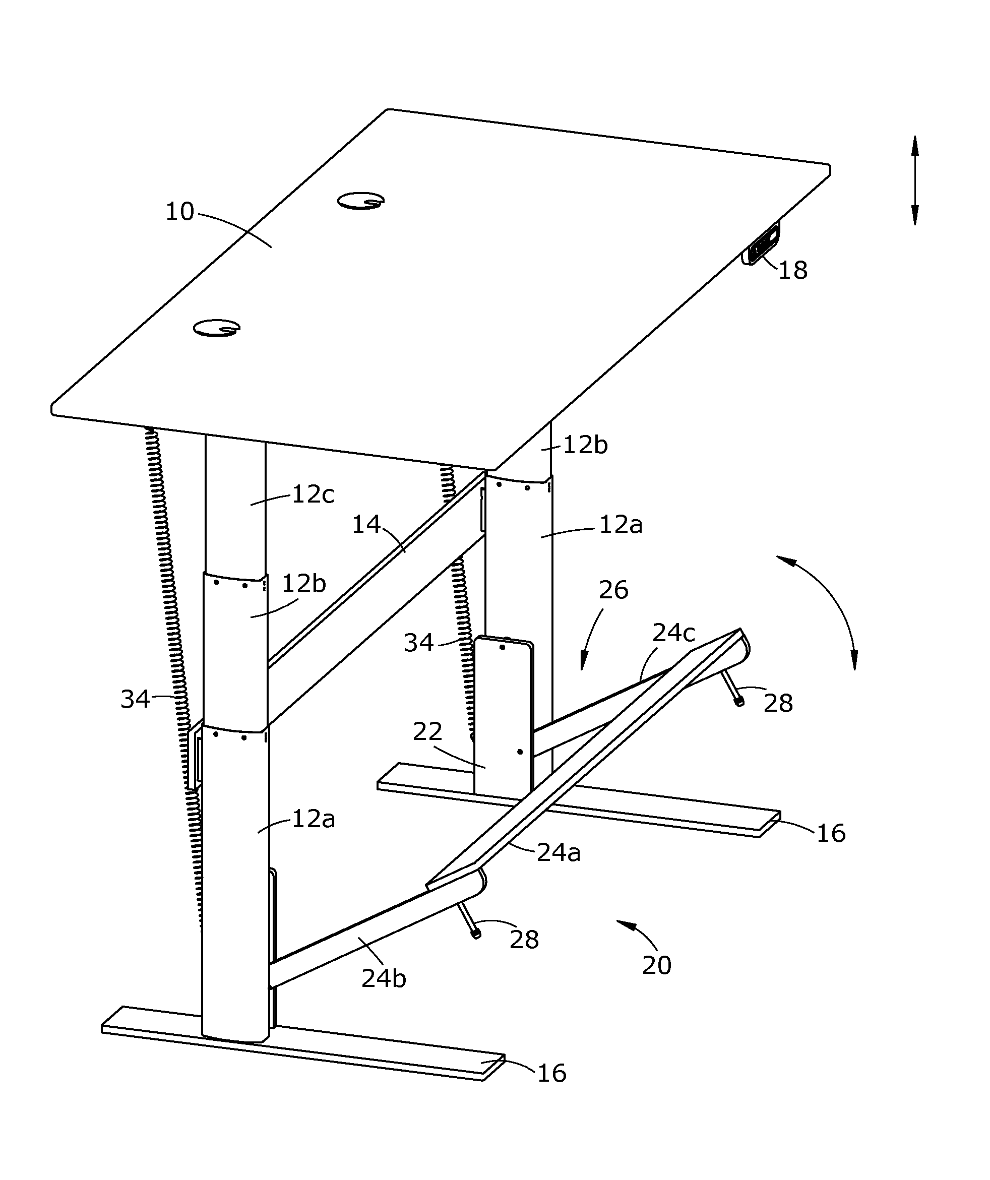
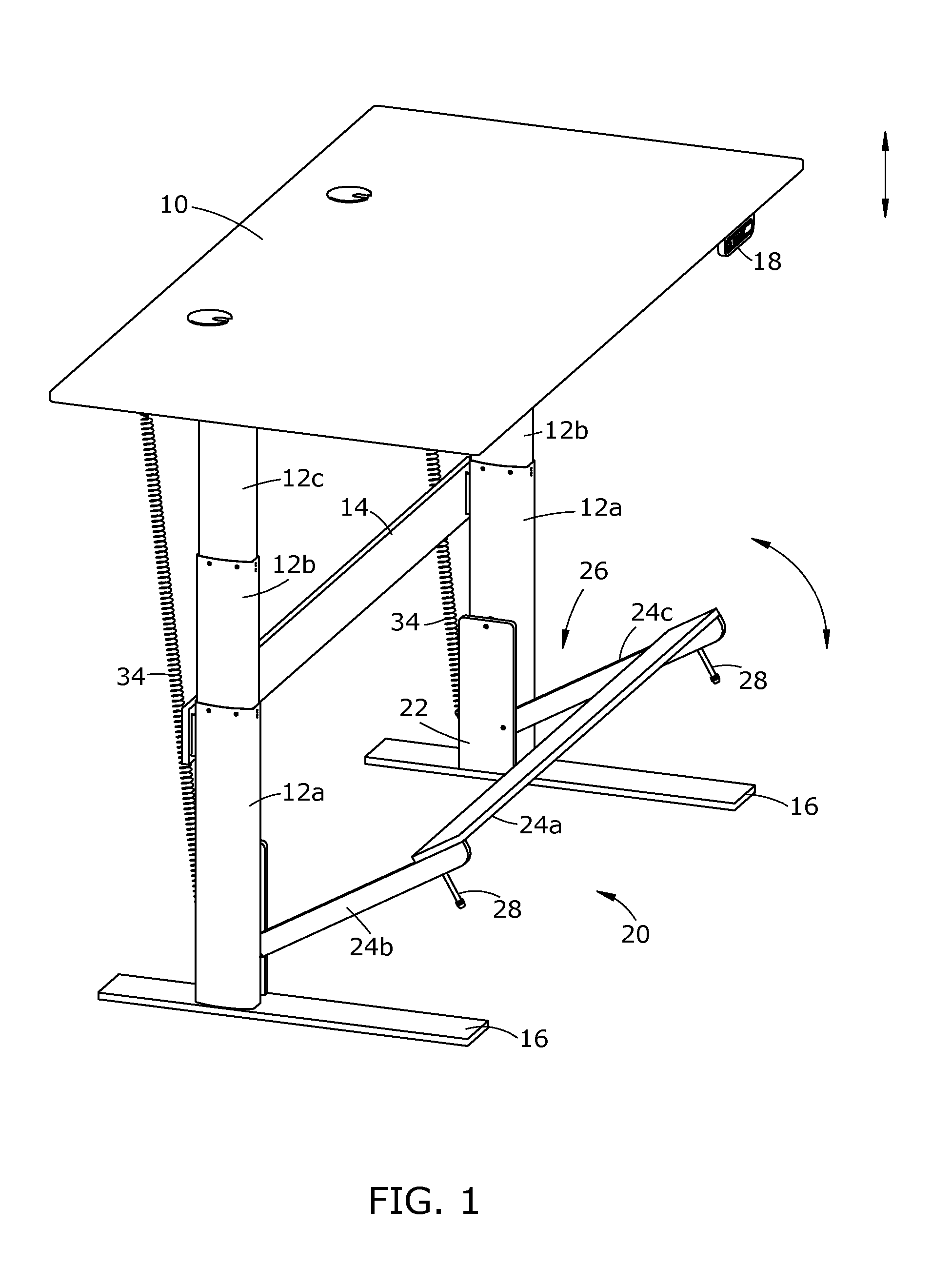
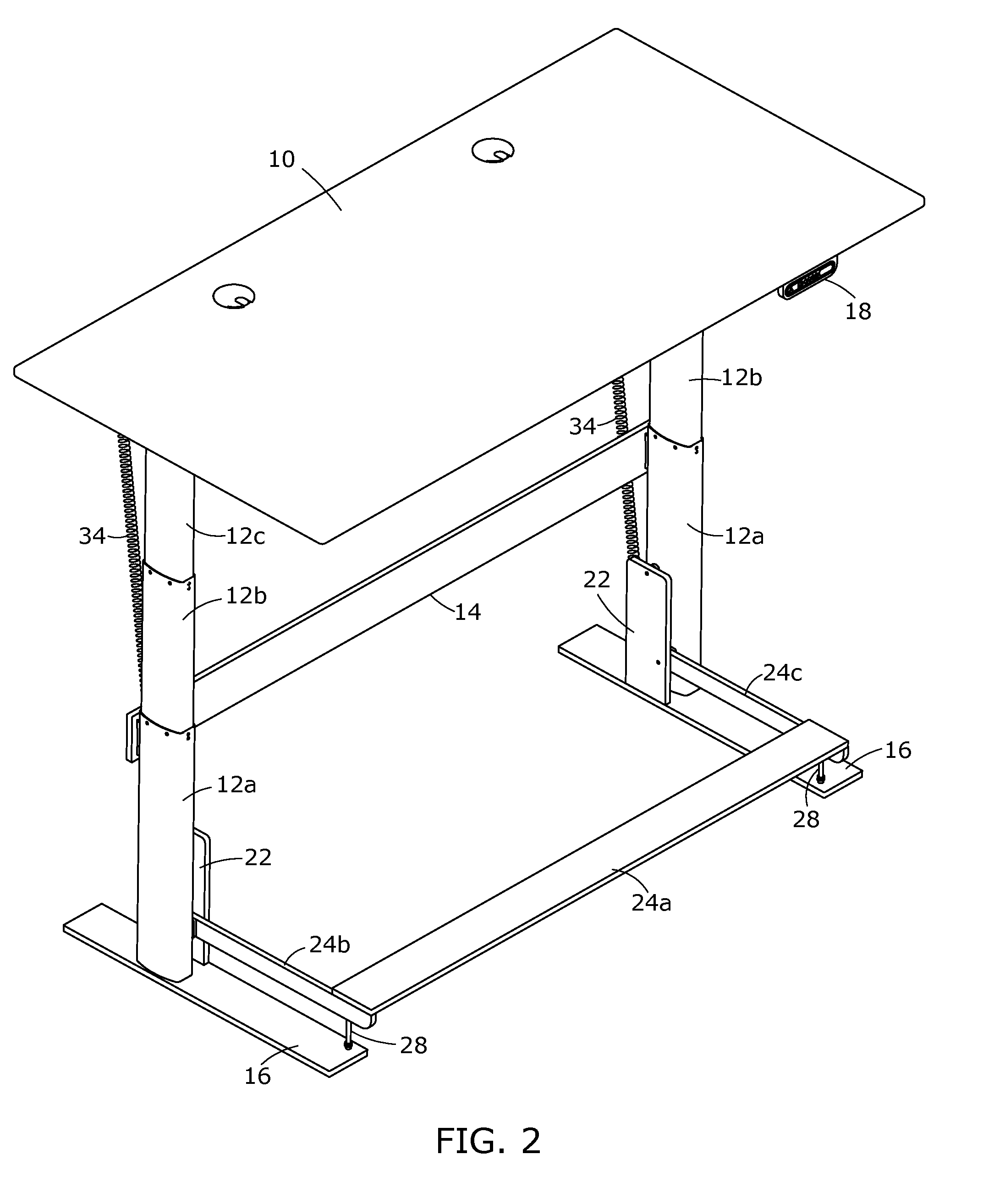
[0031]The electric height adjustable desk assembly exemplified in FIGS. 1-8 comprises a footrest assembly 20 connected to a two legged electric...


PUM


Abstract

An electric height adjustable desk with synchronous moving footrest, method of use, and a rotatable footrest assembly. The desk comprises: a desktop; two electric height adjustable desk leg members; two horizontal base members; and a rotatable footrest assembly. The rotatable footrest assembly comprises: two footrest frame members; two pivot spring connection units; and a rotatable footrest unit comprising a U-shaped foot bar member connected on each end to a pivot spring connection unit. Each spring connection unit comprises: a gas spring; a tension member; and both are connected to a pivot plate member. The tension member and the gas spring work together to rotate the footrest unit to a horizontal position while the desktop rises, and to a vertical position while the desktop is lowered. The tension member may further comprise an extension member to delay rotating the footrest unit until the desktop has reached a selected height.

Description

FIELD OF THE DISCLOSURE[0001]The field of the disclosure is that of office desks. More specifically, the field is height adjustable desks with footrests that adjust simultaneously when a desk moves between a sitting and standing position.BACKGROUND OF THE DISCLOSURE[0002]The adverse effects of prolonged sitting are well documented. Prolonged sitting can cause: an accumulation of metabolites; accelerated disk degeneration leading to disk herniation; premature mortality; chronic diseases such as cardiovascular disease, diabetes, and cancer; and obesity (Pope et al., “Spine Ergonomics”, Annual Review of Biomedical Engineering, Vol. 4: 49-68; and, Pronk et al., “Reducing Occupational Sitting Time and Improving Worker Health: The Take-a-Stand Project, 2011”, Prey Chronic Dis 2012, Vol. 9, Oct. 11, 2012).[0003]Height adjustable desks that position a user to stand and work have become popular to assist a user in avoiding these adverse health effects. But prolonged standing also has its dra...

Claims


Application Information

Patent Timeline
IPC IPC(8): A47B9/02A47C16/02
CPCA47C16/025A47B9/02A47B9/00A47B13/00A47B21/02A47B2200/0097A47C16/02
Inventor HERRING, JASON BRIANGILBREATH, SHANE MICHAEL
Owner NEXTG TECH CO LTD
Learn More