
Imaging device and focusing control method

Active Publication Date: 2016-12-29
FUJIFILM CORP
View PDF7 Cites 2 Cited by
  • Summary
  • Abstract
  • Description
  • Claims
  • Application Information

AI Technical Summary

Benefits of technology

The invention provides an imaging device and a focusing control method that can improve the quality of captured images and enhance the accuracy of phase difference detection for focusing control. This is achieved by connecting detection signals of phase difference detection pixels in different rows to improve the accuracy of detection without compromising the quality of captured images.

Problems solved by technology

However, in the case that the connection of the detection signals is performed with respect to phase difference detection pixels in different rows, there is a probability that an error will be included in a result of a correlation operation, and thus, it is not preferable to constantly perform the connection.

Method used


Image

  • Imaging device and focusing control method
  • Imaging device and focusing control method
  • Imaging device and focusing control method

Examples


Embodiment Construction

[0040]Hereinafter, embodiments of the invention will be described with reference to the accompanying drawings.

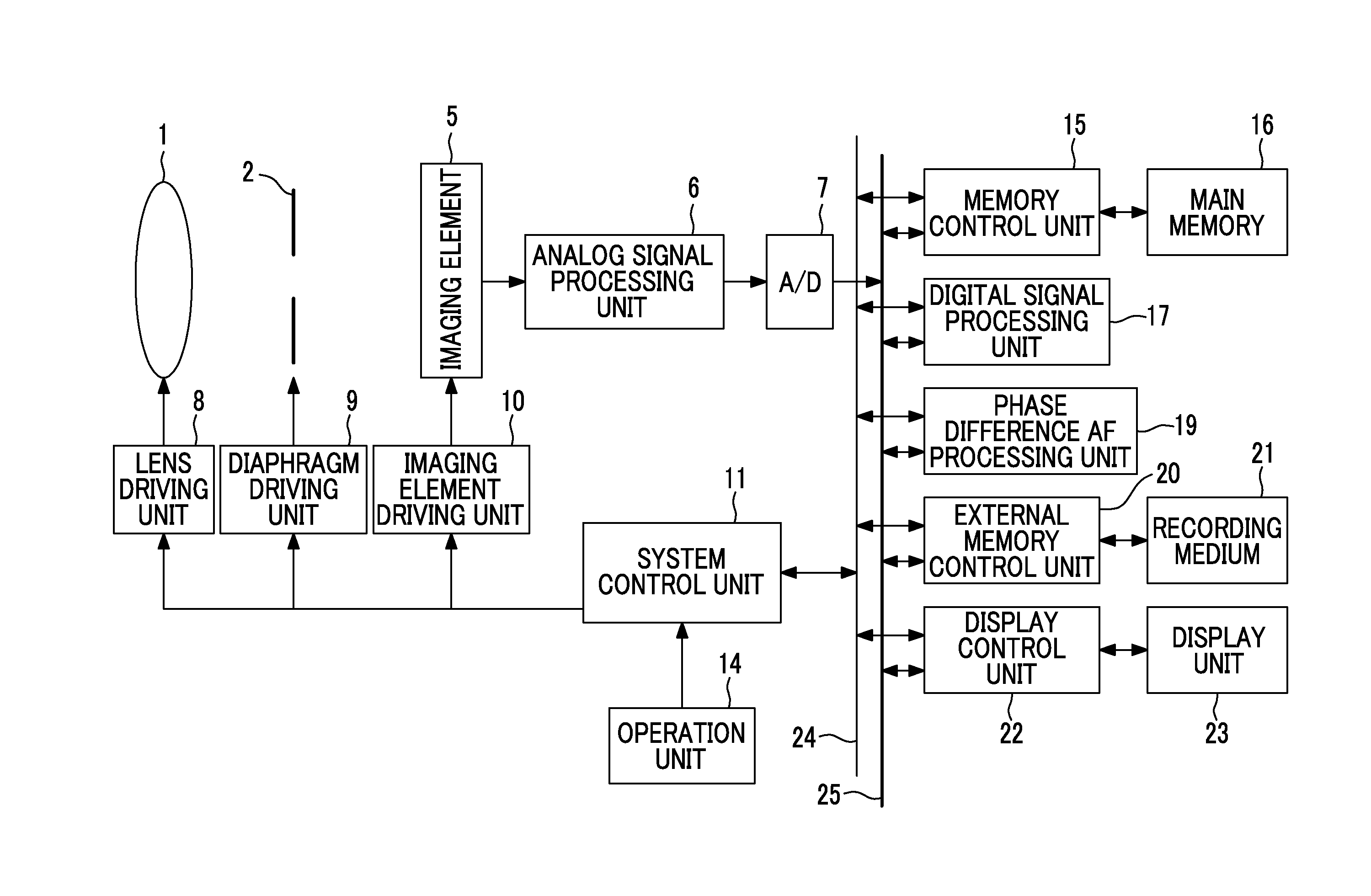
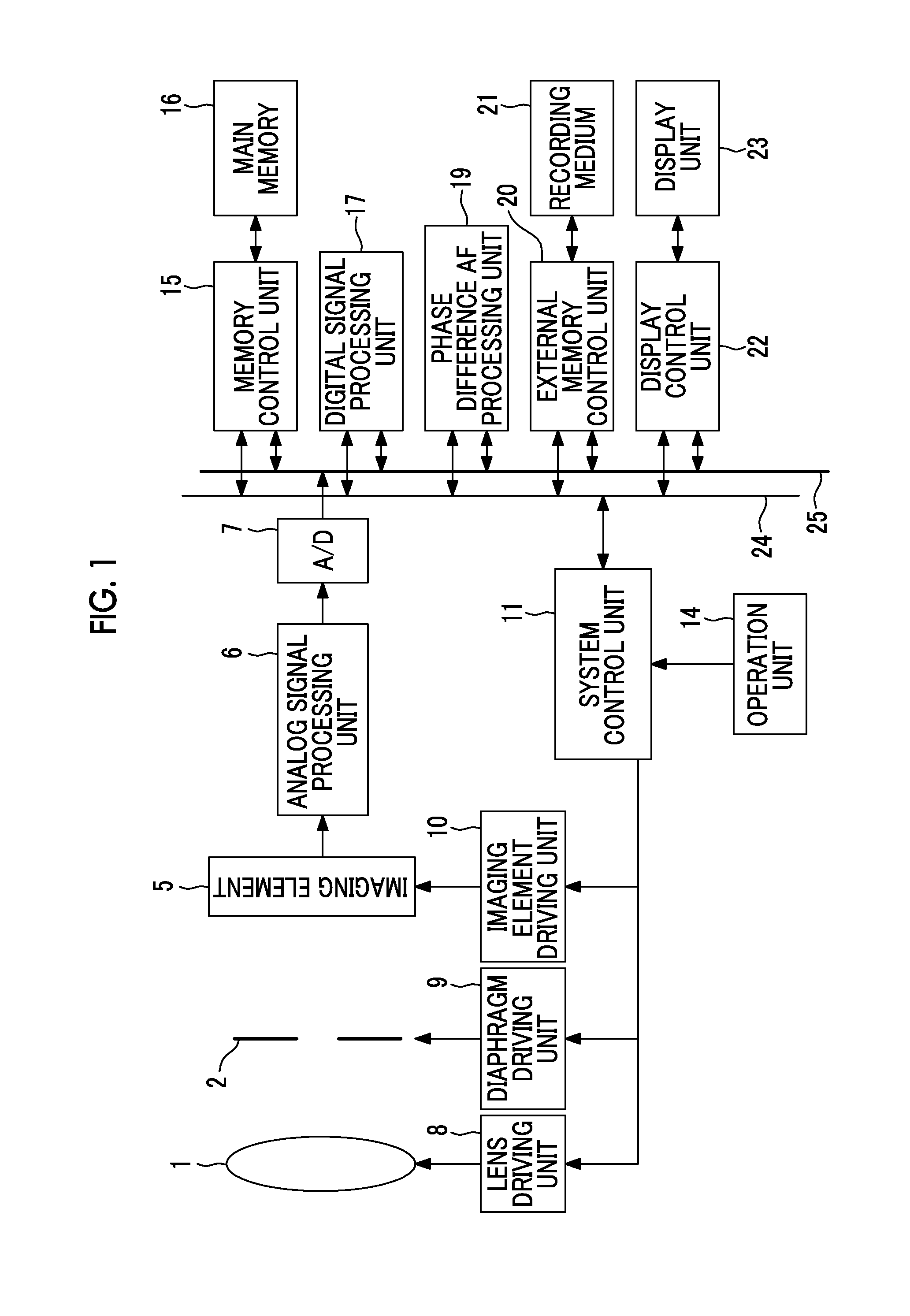
[0041]FIG. 1 is a diagram illustrating a schematic configuration of a digital camera which is an example of an imaging device for describing an embodiment of the invention.

[0042]The digital camera shown in FIG. 1 includes a lens device that includes an imaging lens 1 that includes a focus lens for focus adjustment, a zoom lens, or the like and a diaphragm 2. The lens device forms an imaging optical system.

[0043]The lens device may be fixed to a camera main body, or may be exchanged with another lens device. The imaging lens 1 may include at least the focus lens. The focus lens may be a single focus lens that performs focus adjustment by moving the entirety of the lens system.

[0044]The digital camera includes an imaging element 5 of a CCD type, a CMOS type, or the like that images a subject through the lens device, an analog signal processing unit 6 that is connected to an ou...


PUM


Abstract

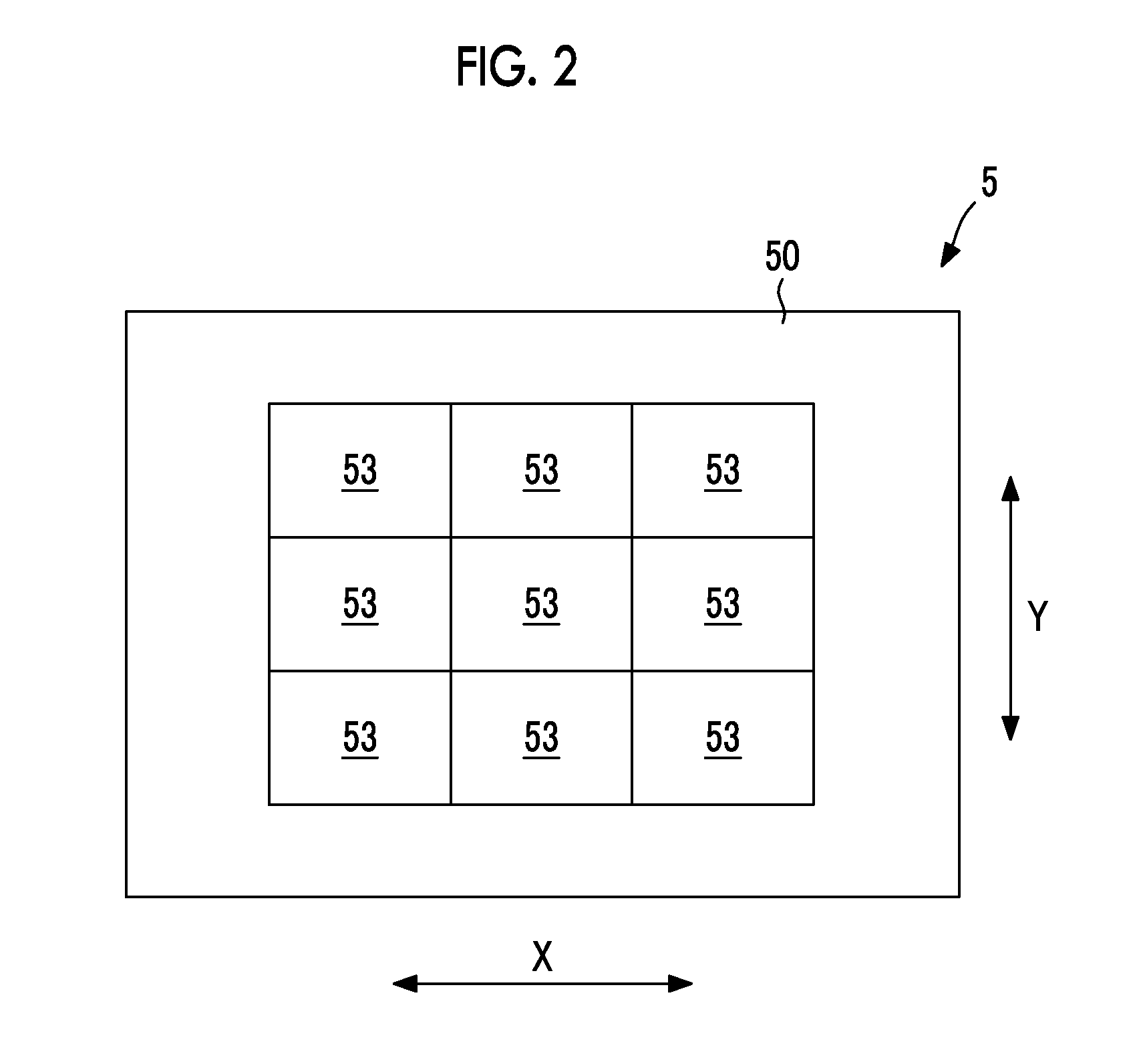
A phase difference AF processing unit (19) connects detection signals of phase difference detection pixels (52A) in an AF area (53), connects detection signals of phase difference detection pixels (52B) in the AF area (53), and performs a correlation operation with respect to detection signal groups after connection to generate a defocus amount when it is determined that a subject image formed in the AF area (53) includes a high frequency component. The phase difference AF processing unit (19) performs a correlation operation with respect to detection signal groups of phase difference detection pixels (52A, 52B) in each pair line in the AF area (53) to generate the defocus amount when it is determined that the subject image formed in the AF area (53) does not include a high frequency component.

Description

CROSS-REFERENCE TO RELATED APPLICATIONS[0001]This application is a Continuation of PCT International Application No. PCT / JP2015 / 050877 filed on Jan. 15, 2015, which claims priority under 35 U.S.C §119(a) to Japanese Patent Application No. 2014-062193 filed on Mar. 25, 2014. Each of the above application(s) is hereby expressly incorporated by reference, in its entirety, into the present application.BACKGROUND OF THE INVENTION[0002]1. Field of the Invention[0003]The present invention relates to an imaging device and a focusing control method.[0004]2. Description of the Related Art[0005]In recent years, according to the increase in resolution of an imaging element such as a charge coupled device (CCD) image sensor or a complementary metal oxide semiconductor (CMOS) image sensor, demand for information devices having an imaging function, such as a digital still camera, a digital video camera, a mobile phone such as a smart phone, or a personal digital assistant (PDA) has rapidly increas...

Claims


Application Information

Patent Timeline
IPC IPC(8): H04N5/232H04N5/369H04N5/378H04N9/04
CPCH04N5/23212H04N5/378H04N5/3696H04N9/045G02B7/28G02B7/34H04N23/672H04N23/63H04N25/704H04N25/134H04N25/75
Inventor AOKI, TAKASHIOHTSUKI, YASUO
Owner FUJIFILM CORP
Learn More