A system and method for predicting thermal-insights of a data center

Active Publication Date: 2016-12-29
TATA CONSULTANCY SERVICES LTD
View PDF4 Cites 7 Cited by
  • Summary
  • Abstract
  • Description
  • Claims
  • Application Information

AI Technical Summary

Benefits of technology

The present patent discloses a method and system for real-time prediction of thermal-insights for a heat dissipating device in a data center cooled by one or more cooling units. The method involves receiving data and operational parameters associated with the data center and cooling units, and partitioning the search space into cells. A statistical model is generated based on the data and operational parameters. Test scenarios are then generated by selecting refinement indices from the statistical model. The test scenarios are computed using computational fluid dynamics simulation. The system includes a processor and memory for executing the method. The technical effects of the present patent include improved accuracy in predicting thermal-insights, improved efficiency in cooling unit operation, and improved data center overall performance.

Problems solved by technology

Not only the change the air flow pattern might be large in magnitude but the time-scale associated with such a change might also be very small.
However, with above mentioned scenarios (such as design changes, CRAC location changes or CRACs with VFDs), the CFD method may found to be very time consuming and expensive.
In such scenario, using CFD modeling turns out to be a very impractical option.
The knowledge of the velocity profile at a location may not provide insights into system control.
Therefore using the velocity as a POD variable may increase the computational complexity of the problem substantially.
In view of the large number of possible flow configurations involved in the data center with VFD installed CRAC; it is very tough to select the set of reference cases that will provide estimation of the temperature to the desired accuracy level.
Therefore, it becomes a challenge to identify exact and appropriate set of the reference cases that may provide accurate prediction of the temperature for a given airflow configuration.
Moreover, it is a challenge to quantify the exact offline CFD effort required for achieving a particular level of accuracy for any given airflow configuration of the CRAC.

Method used


Image

  • A system and method for predicting thermal-insights of a data center
  • A system and method for predicting thermal-insights of a data center
  • A system and method for predicting thermal-insights of a data center

Examples


Embodiment Construction

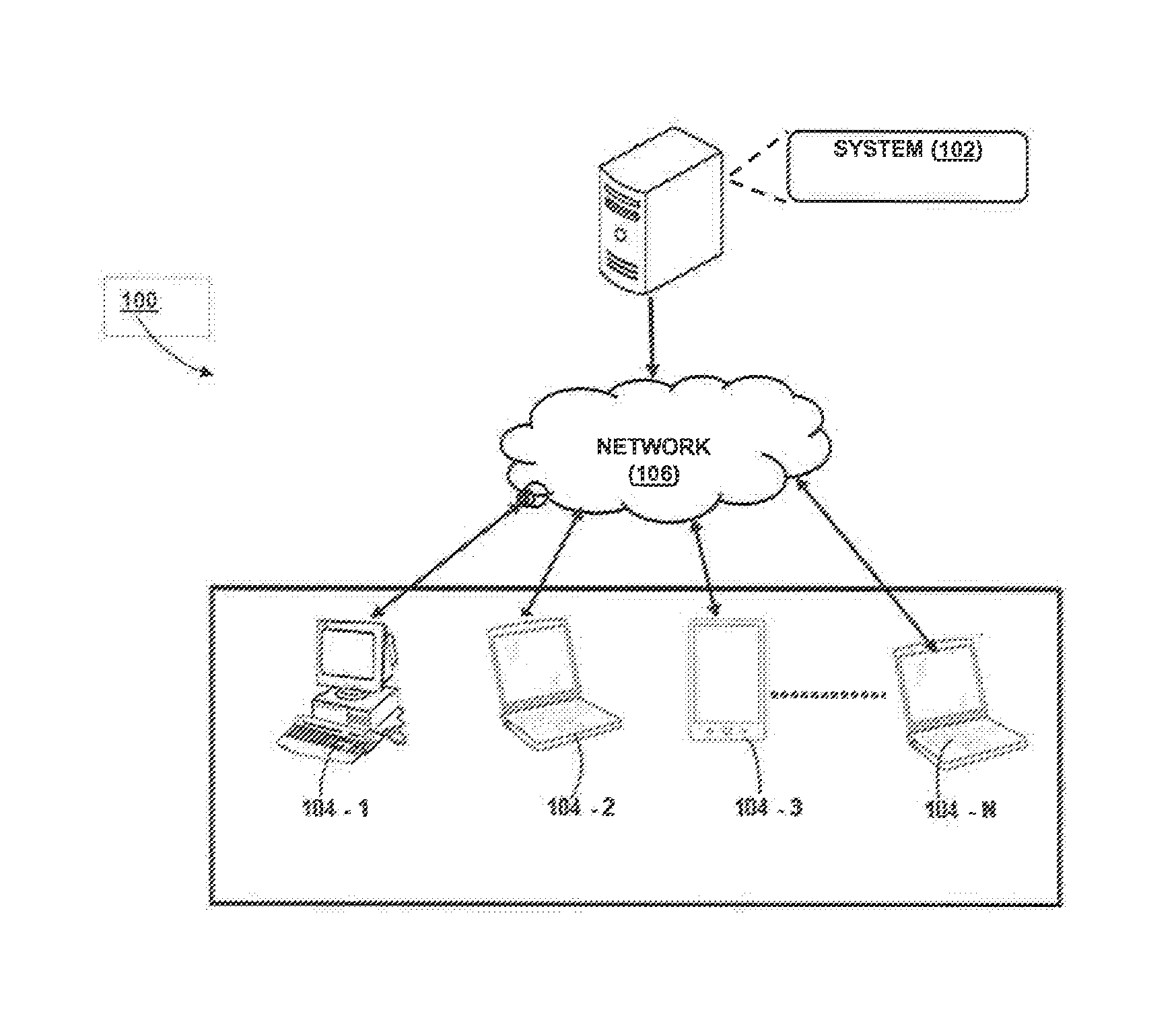
[0015]Exemplary embodiments are described with reference to the accompanying drawings. In the figures, the left-most digit(s) of a reference number identifies the figure in which the reference number first appears. Wherever convenient, the same reference numbers are used throughout the drawings to refer to the same or like parts. While examples and features of disclosed principles are described herein, modifications, adaptations, and other implementations are possible without departing from the spirit and scope of the disclosed embodiments. It is Intended that the following detailed description be considered as exemplary only, with the true scope and spirit being indicated by the following claims.

[0016]The present subject matter discloses an effective and efficient mechanism for prediction of thermal-insights for a heat dissipating device in a data center cooled by one or more cooling units hereinafter referred to as a cooling unit. In one embodiment, the thermal-insights may compri...


PUM


Abstract

Disclosed is a method for real-time prediction of thermal-insights for a heat dissipating device in a data center cooled by one or more cooling units. The method uses a concept of influence mass fractions in conjunction with proper orthogonal decomposition (POD) based reduced order model. It may be understood that, the influence mass fractions may be computed by performing a fixed number of CFD simulations based on mass flow rates of the one or more cooling units. The method further facilitates to identify a set of reference scenarios for a given range of operational parameters of the one or more cooling units impacting the heat dissipating device. The set of reference scenarios may then be provided to the POD in order to predict the thermal-insights of the data center such as a temperature, mass flow rate, and insights into thermal influence of air sources on the heat dissipating device.

Description

PRIORITY CLAIM[0001]This U.S. patent application claims priority under 35 U.S.C. §119 to: India Application No. 3700 / MUM / 2013, filed on 25 Nov. 2013. The corresponding PCT application with application no. PCT / IN2014 / 000120 for this US patent application was filed on 25 Feb. 2014. The entire contents of the aforementioned application are incorporated herein by reference.TECHNICAL FIELD[0002]The present subject matter described herein, in general, relates to a system and method for predicting thermal-insights of a data center based on reduced order modeling techniques.BACKGROUND[0003]Air flow management has been given utmost importance in data center thermal and energy management. A change in the air flow pattern may alter temperature of servers deployed in the data center. Not only the change the air flow pattern might be large in magnitude but the time-scale associated with such a change might also be very small. It has been observed that, the data center often employ variable frequ...

Claims


Application Information

Patent Timeline
IPC IPC(8): G06F17/50G06F17/18
CPCG06F17/5009G06F2217/16G06F17/18G06F11/3006G06F11/3062H05K7/20836G06F2111/10G06F2119/08G06F30/00G06F30/20G06F11/00G06F2113/02G06F30/28
Inventor DEODHAR, ANIRUDHBHAGWAT, HARSHAD GIRISHSINGH, AMAREND KUMARSIVASUBRAMANIAM, ANAND
Owner TATA CONSULTANCY SERVICES LTD
Why Eureka
Try Eureka