
Vertical axis wind turbine

Active Publication Date: 2016-12-29
DME WIND ENERGY CORP
View PDF9 Cites 12 Cited by
  • Summary
  • Abstract
  • Description
  • Claims
  • Application Information

AI Technical Summary

Benefits of technology

The present invention is about designing wind turbines that can capture more wind energy and convert it into electrical energy. The turbine uses stator and rotor blades that work together to reduce back pressure and enhance torque transfer. The stator blades shape the wind to enter the turbine and are designed to guide the wind in a desired direction, resulting in increased efficiency of the device. The stator fins also play a crucial role in directing the wind towards the blade rotation, which significantly improves torque efficiency. Overall, the invention provides an omni-directional wind turbine with improved performance and capacity for wind energy conversion.

Problems solved by technology

Although wind power has the potential to provide a large proportion of the world's electricity needs, the variability in the velocity of the wind often makes it an unreliable power source.
In particular, this variability makes it difficult to construct wind-driven power-generating devices that are effective and efficient under all wind conditions.
By way of non-limiting example, the devices disclosed in U.S. Pat. No. 3,942,909 to Yengst, U.S. Pat. No. 4,632,637 to Traudt, and U.S. Pat. No. 4,818,181 to Kodric concentrate low and moderate winds to produce power and are designed to fold or feather in high winds; while these techniques protect the structural integrity of the device, they also decrease the device's ability to produce power in high winds.
Conversely, by way of non-limiting example, the device disclosed in U.S. Pat. No. 5,391,926 to Staley et al. can harness high winds for power production, but is not capable of generating adequate torque for continual, reliable power generation in low or moderate winds.
However, given their relative complexity compared to horizontal axis windmills, VAWTs continue to suffer from lower cost efficiency than other alternative energy technologies.

Method used


Image

  • Vertical axis wind turbine
  • Vertical axis wind turbine
  • Vertical axis wind turbine

Examples


Embodiment Construction

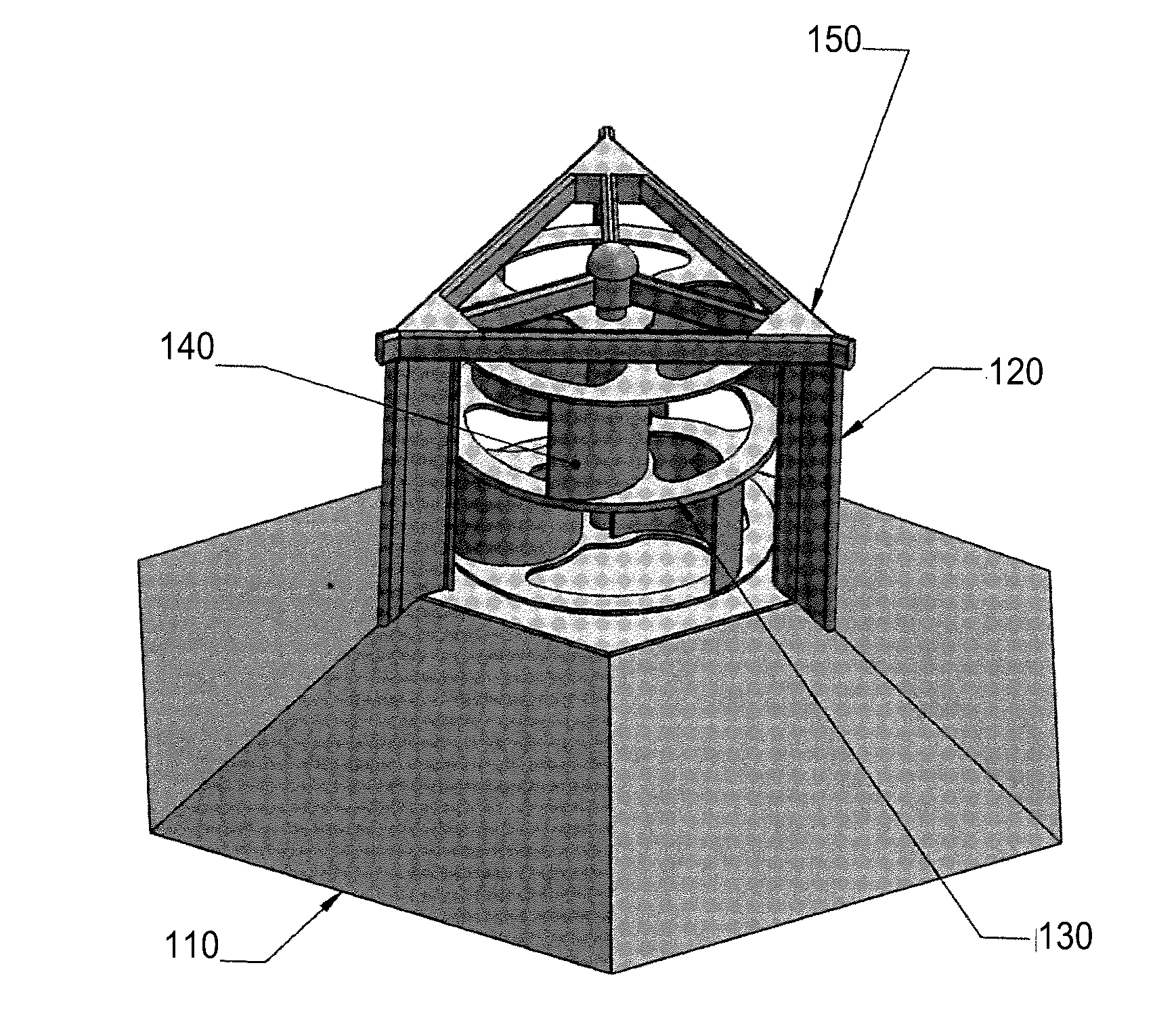
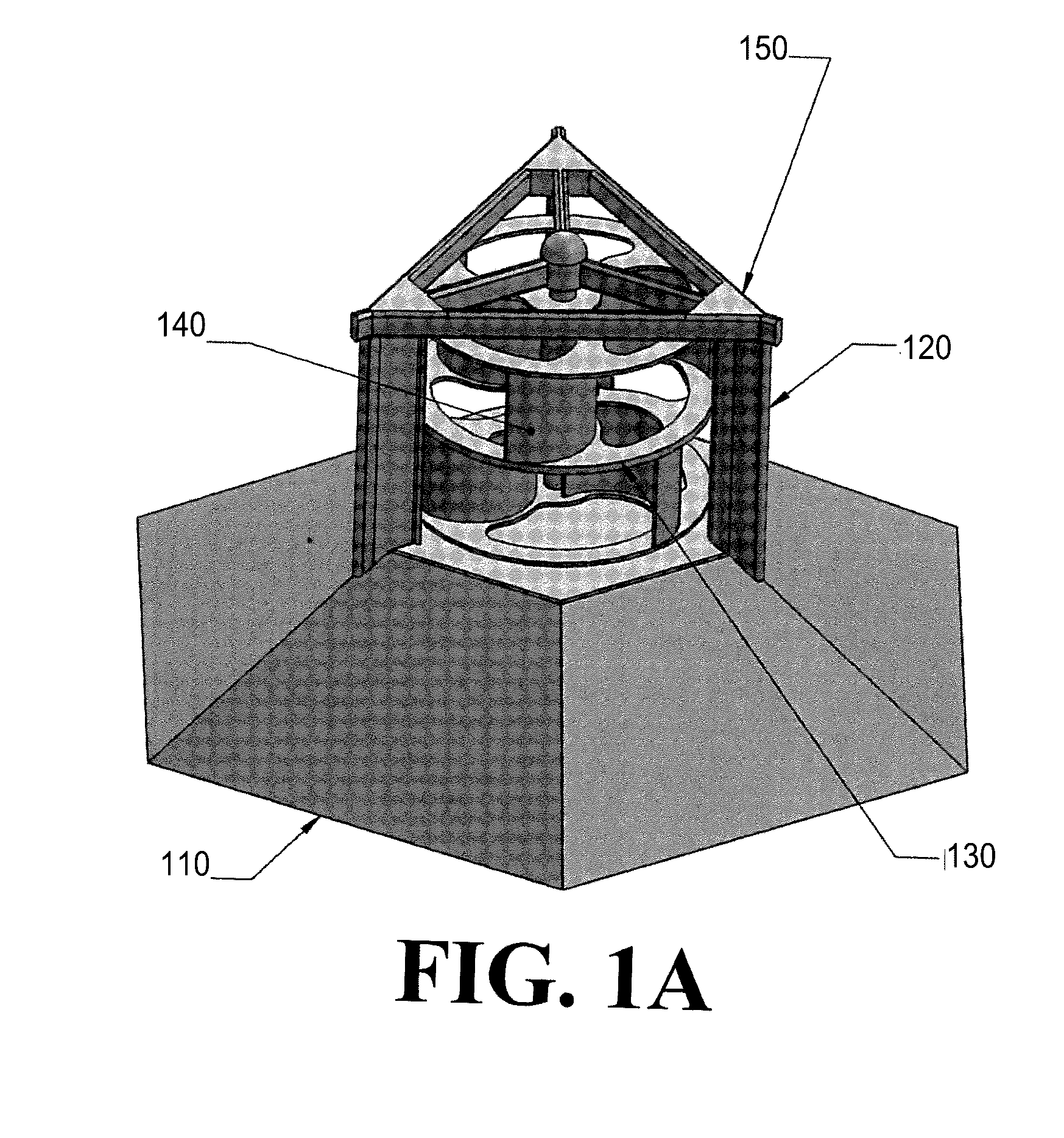
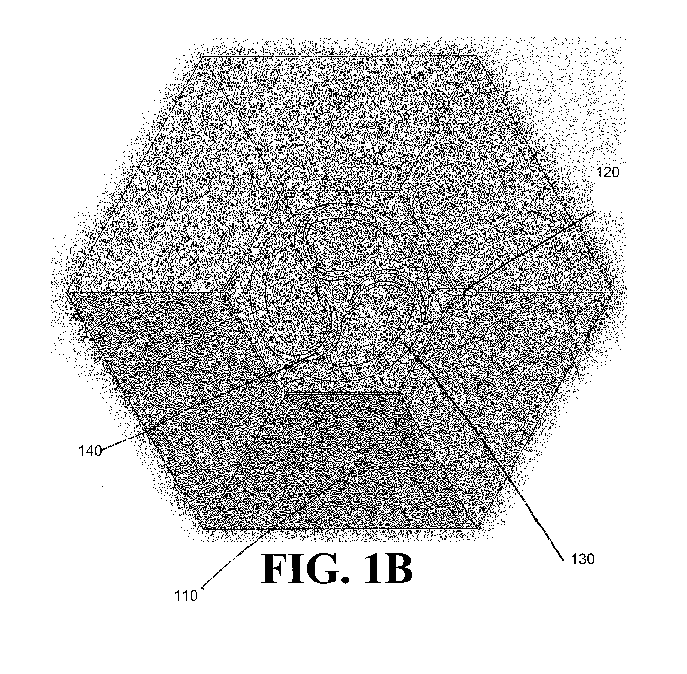
[0006]Certain embodiments include a vertical axis wind turbine, comprising at least one rotor blade, turning a shaft; at least one rotor plate, attached to the at least one rotor blade at one or more of a top and a bottom of the at least one rotor blade; a rotationally symmetric stator skirt, supporting the at least one rotor plate and comprising N identical trapezoidal panels, each trapezoidal panel forming an angle α relative to a horizontal axis, the stator skirt having a horizontal cross-section of a regular polygon having N sides; at least one stator fin, each stator fin being attached at a bottom of the stator fin to the stator skirt and comprising a fin flip, the fin flip being forming an angle β relative to a longitudinal axis of the stator fin and adapted to compress wind and direct the wind to the rotor blades in a predetermined direction; and a top frame, attached to a top of each stator fin.

[0007]In some embodiments, the predetermined direction is clockwise. In other emb...


PUM


Abstract

A vertical axis wind turbine (VAWT) with improved and optimized wind-directing, wind-shaping, and wind-power conversion features is disclosed. The shapes of these features directly affect the ability of the VAWT to use the power of moving air, such as wind, to spin a rotor and create torque on a rotor shaft to generate electricity. The wind-power-conversion mechanical efficiency of the invention is significantly improved over previous efforts, to the point that the invention can convert wind energy into electrical power at a price-to-performance ratio that competes with or surpasses existing alternative energy technologies.

Description

CROSS-REFERENCE TO RELATED APPLICATIONS[0001]This application claims the benefit of U.S. Provisional Patent Application 62 / 184,742, filed 25 Jun. 2015, the entirety of which is incorporated herein by reference.FIELD OF THE INVENTION[0002]This disclosure relates to methods, devices, and systems directed to improving wind directing, shaping, and power conversion, to create torque on a rotor shaft to generate electricity.BACKGROUND OF THE PRESENT INVENTION[0003]Although wind power has the potential to provide a large proportion of the world's electricity needs, the variability in the velocity of the wind often makes it an unreliable power source. In particular, this variability makes it difficult to construct wind-driven power-generating devices that are effective and efficient under all wind conditions. By way of non-limiting example, the devices disclosed in U.S. Pat. No. 3,942,909 to Yengst, U.S. Pat. No. 4,632,637 to Traudt, and U.S. Pat. No. 4,818,181 to Kodric concentrate low and...

Claims


Application Information

Patent Timeline
IPC IPC(8): F03D3/00F03D9/00F03D7/06F03D3/02F03D3/04
CPCF03D3/005F03D3/02F03D3/0454F03D3/0409F05B2240/213F03D9/002F05B2220/30F05B2240/12F03D7/06F03D3/0427Y02E10/74
Inventor REYNA, SID J.CONARRO, PATRICK R.
Owner DME WIND ENERGY CORP
Learn More