
Selectable one-way clutch and vehicle

a one-way clutch and selectable technology, applied in vehicle sub-unit features, transportation and packaging, gearing, etc., can solve the problems of unintentional stopping of the rotation of the rotary member, damage to selectable one-way clutch components, and inability to bring selectable one-way clutches into engagement mode unwillingly, so as to reduce the shock resulting from a fluctuation in driving force and limit damage to selectable one-way clutch elements.

Inactive Publication Date: 2016-12-29
TOYOTA JIDOSHA KK
View PDF17 Cites 21 Cited by
  • Summary
  • Abstract
  • Description
  • Claims
  • Application Information

AI Technical Summary

Benefits of technology

The selectable one-way clutch described in this patent has a unique design that prevents the selector plate from accidentally engaging the fixed plate, which could cause damage or malfunction. This is achieved by maintaining a small clearance between the selector plate and the fixed plate, and delivering lubricating oil to this narrow space through a groove inlet on the fixed plate. This prevents the drag torque that acts on the selector plate when the rotary plate is rotated, and ensures smooth engine starting without any shocks or damage to the components.

Problems solved by technology

Consequently, if the selector plate is rotated to the engagement position, the struts are pushed up into the notches to bring the selectable one-way clutch into the engagement mode thereby stopping the rotation of the rotary member unintentionally.
Thus, if the viscosity of the lubricating oil is too high, the selectable one-way clutch may be brought into the engagement mode unwillingly.
If the selectable one-way clutch used in an automobile is thus brought into the engagement mode unwillingly, shocks may occur in a powertrain and components of the selectable one-way clutch may be damaged.
In addition, shocks resulting from a fluctuation in the driving force can be reduced, and damages on elements of the selectable one-way clutch can be limited.

Method used


Image

  • Selectable one-way clutch and vehicle
  • Selectable one-way clutch and vehicle
  • Selectable one-way clutch and vehicle

Examples


Embodiment Construction

)

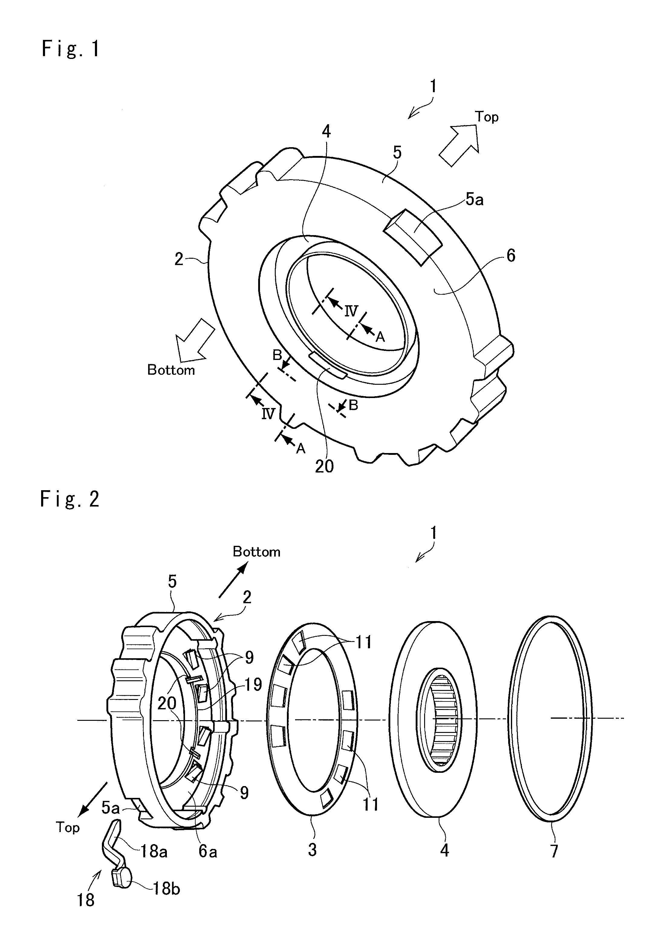
[0042]Preferred embodiments of the present application will now be explained with reference to the accompanying drawings. First of all, a fundamental structure of the selectable one-way clutch (to be abbreviated as the “SOWC” hereinafter) 1 will be explained with reference to the perspective view shown in FIG. 1 and the exploded view shown in FIG. 2. As shown in FIG. 2, the SOWC 1 comprises a pocket plate 2 as a fixed plate, a selector plate 3, and a notch plate 4 as a rotary plate. The pocket plate 2 comprises an outer cylinder 5 and an annular plate 6 formed along an inner circumference of the cylinder 5. The selector plate 3 and the notch plate 4 are held in the cylinder 5 in the order shown in FIG. 2, and a snap ring 7 is fitted into a clearance between an outer circumference of the notch plate 4 and an inner circumference of the cylinder 5 of the pocket plate 2 to close the pocket plate 2.

[0043]Turning to FIGS. 3a and 3b, there is partially shown a cross-section of the SOWC 1 ...


PUM


Abstract

A selectable one-way clutch to prevent an unintentional engagement, and a vehicle having the selectable one-way clutch are provided. The selectable one-way clutch comprises a fixed plate, a rotary plate opposed to the fixed plate, and a selector plate interposed between the fixed plate and the rotary plate. A strut is held on the fixed plate in a pivotal manner to be selectively engaged with the rotary plate. The selector plate is rotated between an engagement position at which the strut is allowed to project toward the rotary plate to be engaged therewith, and a disengagement position at which the strut is pushed into the fixed plate to be disengaged from the rotary plate. A groove inlet is formed on the inner face to introduce oil to a clearance between the fixed plate and the selector plate.

Description

[0001]The present invention claims the benefit of Japanese Patent Applications No. 2015-130343 filed on Jun. 29, 2015 and No. 2016-090900 filed on Apr. 28, 2016 with the Japanese Patent Office, the disclosure of which is incorporated herein by reference in its entirety.BACKGROUND[0002]Field of the Invention[0003]Preferred example relates to the art of a selectable one-way clutch that transmits torque when rotated in a predetermined direction and overruns when rotated in an opposite direction, and to a vehicle having the selectable one-way clutch.[0004]Discussion of the Related Art[0005]JP-A-2015-77846 describes one example of the selectable one-way clutch of this kind used in a hybrid vehicle having an engine and a motor. In the conventional selectable one-way clutch, a selector plate is interposed between a fixed disc and a rotary disc while being allowed to rotate within a predetermined range. A plurality of struts are held in pockets formed on the fixed disc in such a manner to b...

Claims


Application Information

Patent Timeline
IPC IPC(8): B60K6/383F16H37/08B60K6/442F16H3/72F16D41/12B60K6/365
CPCB60K6/383F16D41/125B60K6/365B60K6/442F16H3/728B60Y2400/73Y10S903/913Y10S903/91B60Y2200/92B60Y2306/03B60Y2400/427F16H37/0813F16D41/08B60K6/445F16D41/14Y02T10/62
Inventor KUROSAKI, YUKISHIOIRI, HIROYUKIKOMADA, HIDEAKISHIBATA, HIROYUKIYASUI, HIROKI
Owner TOYOTA JIDOSHA KK
Learn More