
Overmolded low cost cutlery

a low-cost, overmolded technology, applied in the field of articles, can solve the problems of requiring relatively long cycle times, creating insufficient and imperfect quality pieces, and existing techniques not meeting the need of so-called

Inactive Publication Date: 2016-12-29
MODERN PACKAGING LLC
View PDF33 Cites 9 Cited by
  • Summary
  • Abstract
  • Description
  • Claims
  • Application Information

AI Technical Summary

Benefits of technology

The invention is about a molded object that has a decorative feature on its surface. The decorative feature is partially or fully outlined by a wall and is designed to have a connection element that allows the first material to fill it. A second material can then be added to the surface of the object to further enhance its appearance. The technical effect of this invention is that it allows for the creation of molded objects with both a decorative feature and a connection element for further enhancement.

Problems solved by technology

In short, these known, general state-of-the-art processes have considerable drawbacks in that specific, numerous, and therefore costly or oversized tools, must be used, requiring relatively long cycle times and often creating insufficient and imperfect quality pieces.
Thus, as can be seen, the existing techniques do not meet the need that exists for so-called “aesthetic” pieces such as those currently needed for the preparation of smaller articles such as utensils.

Method used


Image

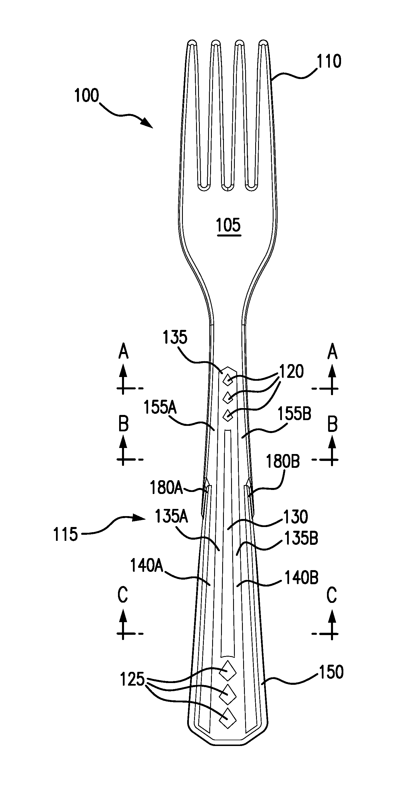
  • Overmolded low cost cutlery
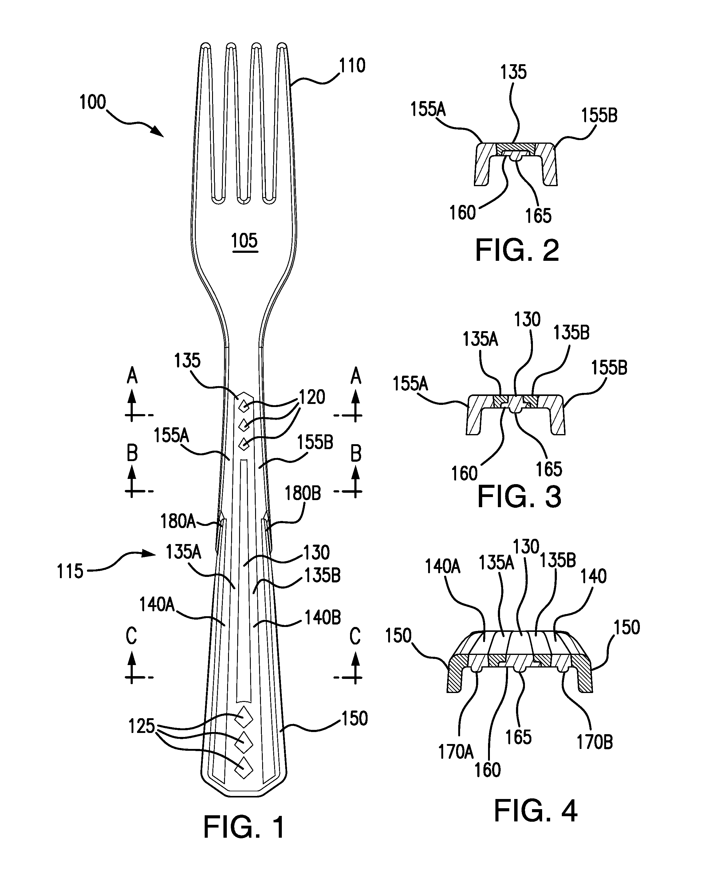
  • Overmolded low cost cutlery
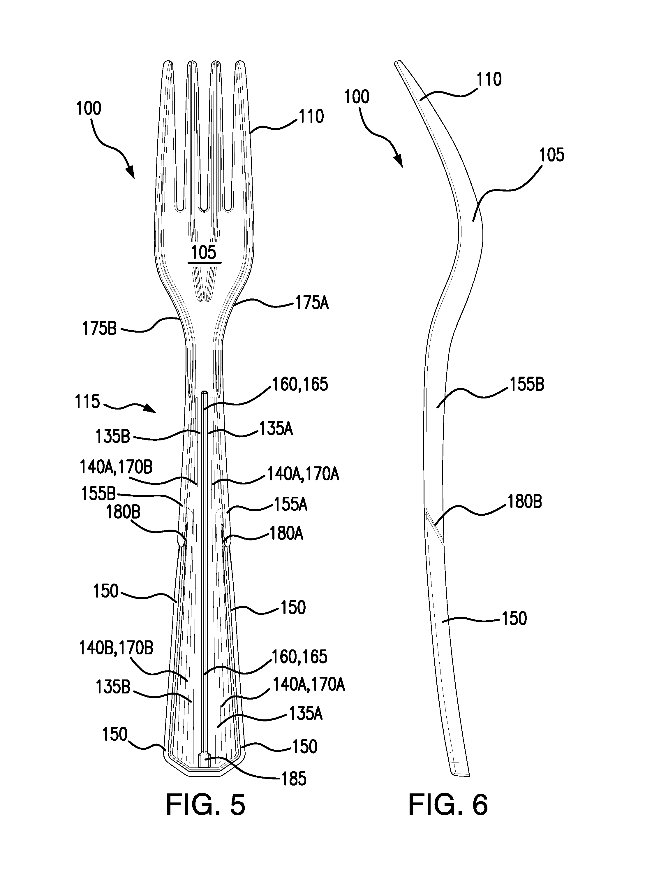
  • Overmolded low cost cutlery

Examples


second embodiment

[0072]FIGS. 7 to 14 illustrate the invention. These drawings illustrate an overmolded fork 200 that includes working end 205, tines 210 and a handle portion 215. The front or top of the fork 200 includes a pattern that includes decorative features including a wall member that forms a sidewall 220 that outlines the handle 215. A further decorative feature in the form of a teardrop shaped insert 225 is provided. These decorative features 220, 225 are part of the first molded structure and are made of the same first material. The first molded structure also includes the working end 205 of the fork 200 and the tines 210.

[0073]The second molded structure that is overmolded onto the first molded structure is a larger elongated insert 230 which surrounds the teardrop shaped insert 225 and which extends towards the working end of the handle. The elongated insert 230 includes as a decoration a number of raised bumps 235 which are positioned along the periphery or within insert 230. These pro...

third embodiment

[0089]FIGS. 16, 17, 20, 22 and 23 illustrate the invention. FIG. 16 illustrates an overmolded fork 300 according to the present invention that includes working end 305, tines 310 and a handle portion 315. The front or top of the fork includes a pattern that includes decorative features including a sidewall 320 and an elongated teardrop shaped insert 325 which extends over most of the top surface of the handle 315. The insert 325 surrounds a number of circular, flat dots 330 which are of a different color than the insert 325. The working end 305, tines 310, sidewall 320 and dots 330 are all included in the first molded structure and are made of the same first material. If desired, the dots can be provided as protruding or recessed bumps. The insert 325 is filled within the sidewall 320 and around the dots 330 and extends to the rear side of the fork 300 where a smaller teardrop shaped insert 335 is provided. The remainder of the back of the handle 315 is made of the first molded stru...

fourth embodiment

[0093]FIGS. 18, 19, 21, 24 and 25 illustrate the invention. FIG. 18 illustrates an overmolded fork 400 according to the present invention that includes working end 405, tines 410 and handle portion 415. The front or top of the fork includes a pattern that includes decorative features such as lines 425, 430435 that are provided by the first molded structure. Line 425 has expanded upper and lower portions to provide further ornamentation to the handle 415. These lines along with the working end and tines represent the first molded structure. Contrasting colors are provided by the second molded structure which includes bands 440, 445, 450 and 455 all of which are joined together at the bottom of the handle 415. The first molded structure also include side portions 460 and 465 in the upper portion of the handle 415.

[0094]To facilitate the overmolding of this article, an angled shut off 490, 495 is provided so that the first molded structure easily accommodates the second material to for...


PUM

PropertyMeasurementUnit
draft anglesaaaaaaaaaa

Abstract

The invention relates to a molded article that includes a first molded structure that includes a working end, a bottom end, at least one wall member extending from the working end to the bottom end of the structure and at least partially or fully outlining a handle for the article, at least one decorative feature that resides on the handle surface of the article, and a connecting element that provides a flow path for first material to fill the decorative feature(s). The first molded structure is configured and dimensioned to receive a second material that also resides on the handle surface surrounding the decorative feature(s). The second shot molded structure is molded from the second material and includes surface portions that form top and bottom surfaces of the handle and that surround or encompass but do not cover the decorative feature(s) of the first molded structure.

Description

[0001]The application claims the benefit of U.S. application No. 62 / 185,330 filed Jun. 26, 2015, the entire content of which is expressly incorporated herein by reference thereto.BACKGROUND[0002]The invention relates to articles that include design features that facilitate rapid production when utilizing a two-shot overmolding process to produce low-cost articles such as disposable cutlery.[0003]It is generally known to use a two-shot molding process to manufacture articles having different colors or different features. For example, US patent publications 2011 / 0219631 and 2013 / 0047528 and U.S. Pat. Nos. 5,049,343, 7,487,007, 7,811,497, 8,012,398, 8,414,813 and 8,747,100 disclose various molding production techniques. In short, these known, general state-of-the-art processes have considerable drawbacks in that specific, numerous, and therefore costly or oversized tools, must be used, requiring relatively long cycle times and often creating insufficient and imperfect quality pieces. T...

Claims


Application Information

Patent Timeline
Patent Type & Authority Applications(United States)
IPC IPC(8): A47G21/02B29C45/16B29C45/02B26B3/02A47G21/04
CPCA47G21/023B26B3/02A47G21/04B29L2031/286B29C45/16B29K2021/00B29K2075/00B29C45/02A47G21/02B29C45/162B29C33/44B29C45/0046B29C2045/0027B29C2045/1682B29C2045/1687
Inventor SHAPIRO, BENJAMINWLEZIEN, CHRISTOPHERRATHGEBER, MARTINSHAPIRO, MATTHEW
Owner MODERN PACKAGING LLC
Learn More