
Heated Cable Cover for Gutter Debris Preclusion Devices

Active Publication Date: 2016-12-22
GUTTERGLOVE
View PDF48 Cites 5 Cited by
  • Summary
  • Abstract
  • Description
  • Claims
  • Application Information

AI Technical Summary

Benefits of technology

The patent describes a heat cable cover for gutter guard systems. The cover has a body that attaches to the gutter debris preclusion device or the gutter, with a lip that extends beyond the gutter. The front member and middle portion have a channel that receives the heat element. The cover can be attached to the gutter debris preclusion device or the gutter. The channel has a cross-sectional shape of a partial rectangle, ellipse, or sinusoidal curve. The front member has a bottom portion that extends towards the channel. The cover is designed to protect the heat cable from damage and to prevent debris from entering the gutter.

Problems solved by technology

One problem experienced by all different types of gutter guard systems in certain environments is that when freezing temperatures are encountered, water on and adjacent the gutter guard will freeze, and preclude water from passing into the gutter.
When such gutter guard performance is inhibited, freeze and thaw cycles can result in dangerously large icicles forming off of edges of the gutters or other portions of the roof.
Furthermore, the weight of the snow and ice on the gutter guard can potentially damage the gutter or gutter guard, or at least require that it be designed to withstand high loads, increasing the complexity, and cost of the gutter guards.
Another problem with non-de-icing gutter guards is “ice dams” can form.
Particularly, the heat from the inside of a building can transfer out to the roof and begins melting snow.
Then the water begins to pool above the ice dam and then the melted snow, with nowhere else to go, will tend to find it's way through the roof and into the home, causing damage.

Method used


Image

  • Heated Cable Cover for Gutter Debris Preclusion Devices
  • Heated Cable Cover for Gutter Debris Preclusion Devices
  • Heated Cable Cover for Gutter Debris Preclusion Devices

Examples


Embodiment Construction

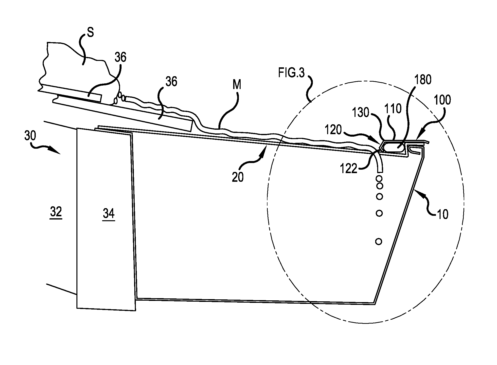
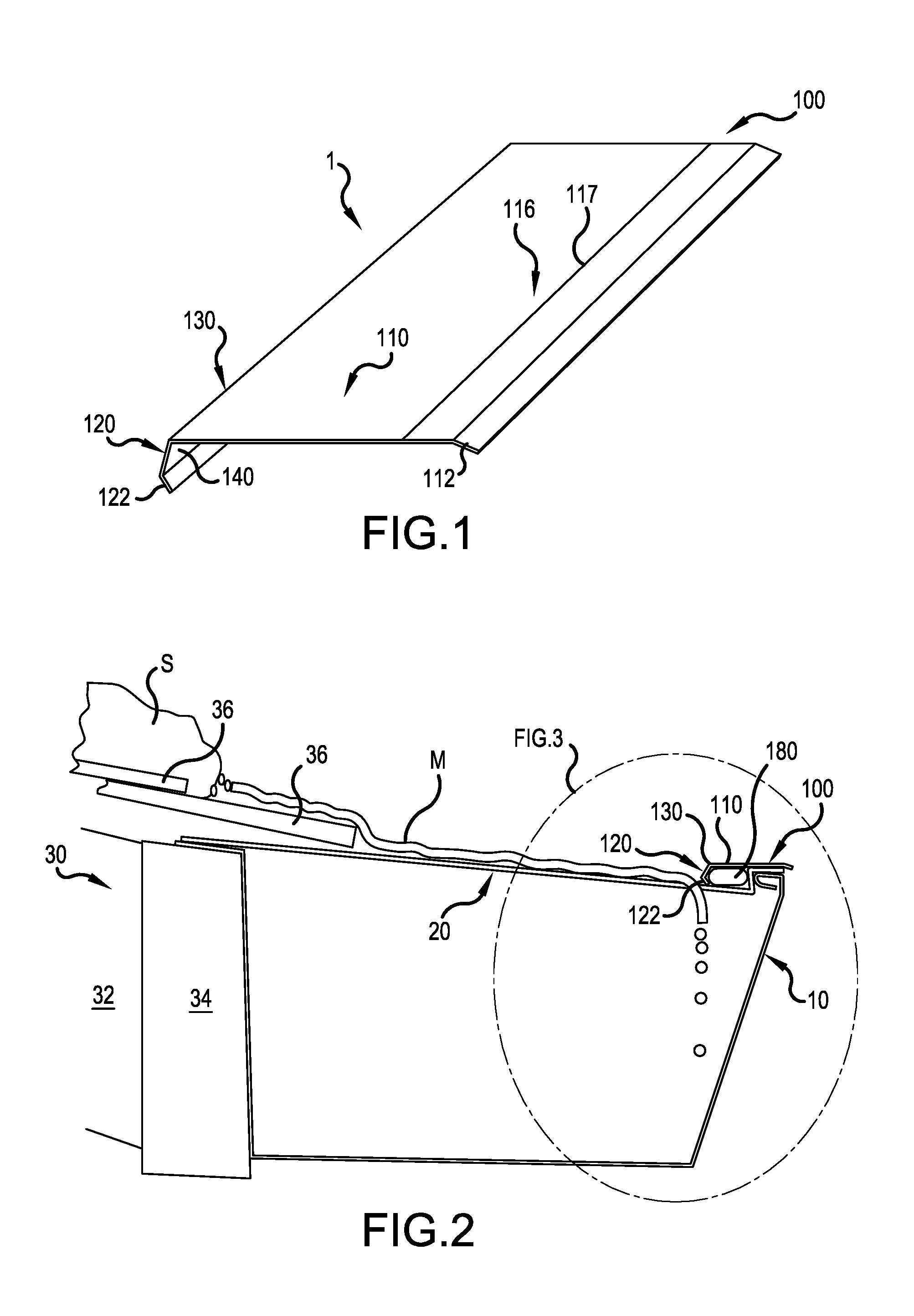
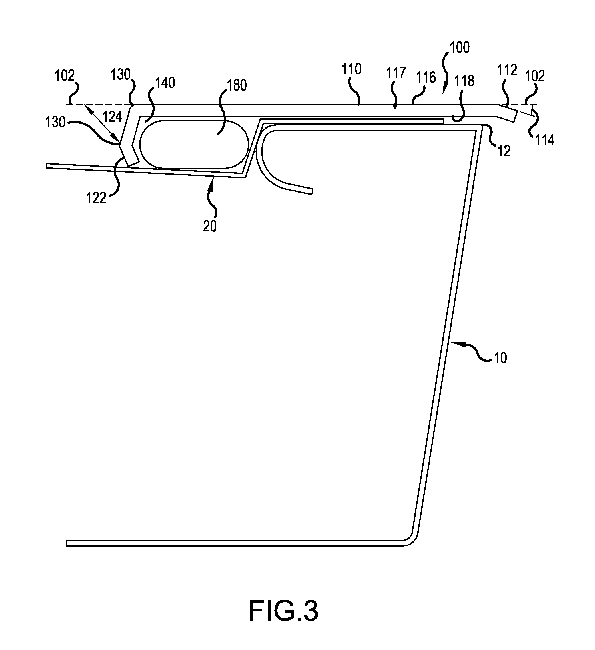
[0026]Referring to the drawings, wherein like reference numerals represent like parts throughout the various drawing figures, FIGS. 1- 3 display a cover 100 for use with a debris preclusion device or gutter guard made in accordance with the present invention. FIG. 1 is a top left side perspective view of the cover device 100 made in accordance with the invention. The device 100 includes a main body 110, a front member or leg 120 and a middle member 130. FIG. 2 illustrates a side view of the cover 100 when in use in connection with a gutter 10 and a gutter debris preclusion device (gutter guard) 20. FIG. 3 illustrates a side view of the illustration and the device 100 of FIG. 2 taken along the line FIG. 3 in FIG. 2. A heat element 180 is held adjacent to the gutter debris preclusion device 20 with the cover 100. The cover 100 includes a channel 140 defined by a portion of the main body 110, the front member 120 and the middle portion 130. The heat element 180 is disposed substantiall...


PUM


Abstract

The present invention includes a cover for use with a heat element and gutter debris preclusion devices. The cover includes a body, a front member, and a middle portion disposed between the body and the front member. The body includes a lip being operably configured to extend beyond an outer edge of the gutter when the cover is in use. The cover also includes a channel defined by the middle portion and at least the front member, wherein the channel is operably configured to receive the heat element. The cover is operably configured to hold the heat element to the gutter debris preclusion device. When the heat element is energized it will generate heat. The cover will enable the generated heat to transfer to the gutter debris preclusion device and to a gutter to which it is attached.

Description

CROSS-REFERENCE TO RELATED APPLICATION(S)[0001]This application claims the benefit of U.S. Provisional Patent Application No. 62 / 119,009, filed Feb. 20, 2015, the contents of which are hereby incorporated by reference in its entirety.FIELD OF THE INVENTION[0002]This invention relates to gutter debris preclusion devices for rain gutters and similar structures for keeping leaves and other debris out of the rain gutters. More particularly, this invention relates to de-freezing rain gutter debris preclusion devices.BACKGROUND OF THE INVENTION[0003]There are many types of conventional gutter debris preclusion devices (gutter guard systems). These gutter guard systems generally span the opening of a gutter and are designed to keep leaves and debris from entering a gutter while allowing the water to pass through to the gutter. One problem experienced by all different types of gutter guard systems in certain environments is that when freezing temperatures are encountered, water on and adjac...

Claims


Application Information

Patent Timeline
IPC IPC(8): E04D13/076E04D13/064
CPCE04D13/0762H05B2214/02H05B3/56E04D13/064H05B3/06H05B2203/014E04D13/076
Inventor LENNEY, ROBERT C.
Owner GUTTERGLOVE
Learn More