Shear Wave Imaging Method and Installation for Collecting Information on a Soft Solid

a soft solid and imaging method technology, applied in the field of shear wave imaging methods, can solve the problems of difficult implementation of techniques, tedious and laborious detection methods based on compression wave propagation, and inability to consider elastography methods as elastography methods, etc., and achieve the effect of convenient implementation

Inactive Publication Date: 2016-12-22
INST NAT DE LA SANTE & DE LA RECHERCHE MEDICALE (INSERM) +1
View PDF0 Cites 8 Cited by
  • Summary
  • Abstract
  • Description
  • Claims
  • Application Information

AI Technical Summary

Benefits of technology

[0011]The invention aims at solving the problems of known elastography methods with a new method which is efficient to generate shear waves, even in deep target regions of a soft solid. More generally speaking, the invention aims at providing a shear wave imaging method which is easy to implement and can be used for elastography or electric tomography.

Problems solved by technology

Thus, a detection method based on the propagation of compression waves cannot be considered as an elastography method.
This is tedious and requires a high expertise.
However, this technique is difficult to implement when the target zone is far from the transducer array, for instance in deep organs.
Actually, the ultrasound energy deposition quickly decreases with depth, and under such circumstances, the ultrasound radiation force cannot create effective shear waves propagation.
Therefore the technology of US-A-2009 / 018432 is not adapted to shear wave elastography.
Thus, shear waves generation in deep target regions is also difficult to obtain with these techniques.

Method used


Image

  • Shear Wave Imaging Method and Installation for Collecting Information on a Soft Solid
  • Shear Wave Imaging Method and Installation for Collecting Information on a Soft Solid
  • Shear Wave Imaging Method and Installation for Collecting Information on a Soft Solid

Examples


Embodiment Construction

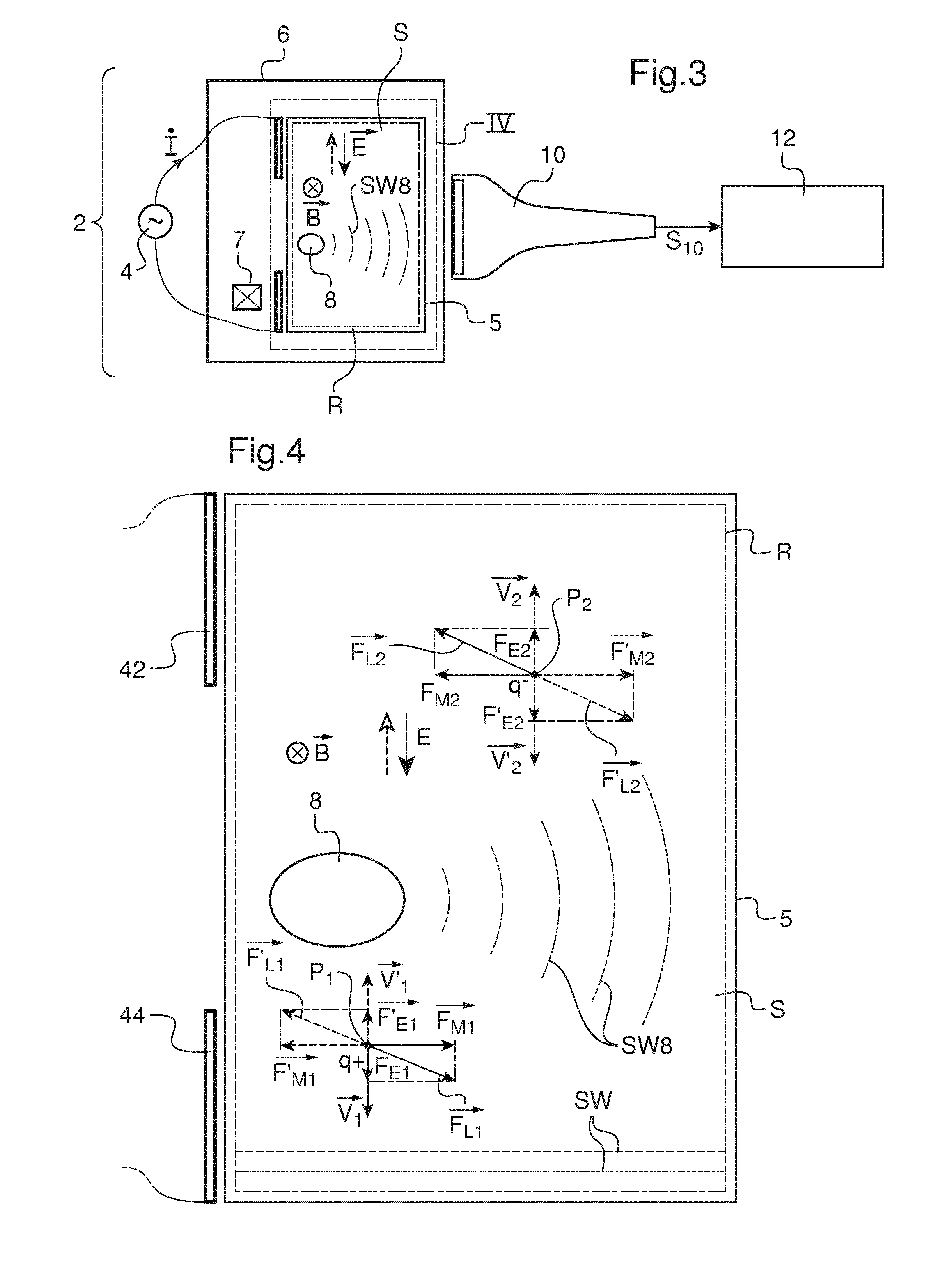
[0048]The installation 2 represented on FIGS. 1 and 2 includes an alternative current generator 4 which is connected to a first electrode 42 and to a second electrode 44 located on either sides of an electrically conductive soft solid S housed in a box 5. Box 5 is optional and can be omitted if soft solid S stands on its own. Soft solid S can be a portion of an animal body, such as a muscle. In such a case, no box 5 is needed. Soft solid S is considered to be electrically conductive insofar as its conductivity is between 103 and 1 Siemens per meter (S / m) for frequencies between 1 Hz and 10 kHz. In other words, at least some particles of soft solid S are electrically loaded, with a positive or negative charge q+ or q−.

[0049]One considers a region R of soft solid S to be studied by elastography. In the example of FIGS. 1 and 2, region R corresponds almost to the totality of solid S located in box 5, between electrodes 42 and 44. Alternatively, region R can correspond to a smaller port...


PUM


Abstract

This shear wave imaging method, for collecting information on a target region (R) of a soft solid (S), comprises at fi least the steps a) of generating at least one shear wave (SW) in the target region, and b) of detecting a propagation pattern of the shear wave in the target region. Step a) is realized by applying to particles of the target region (R) some Lorentz forces resulting from an electric field (E) and from a magnetic field (B). At least one of the electric field (E) and the magnetic field (B) is variable in time, with a central frequency (fo) between 1 Hz and 10 kHz. Alternatively, both the electric and magnetic fields (E, B) are variable in time, with a central difference frequency (Δfo) between 1 Hz and 10 kHz. The shear wave imaging installation comprises a first system (4, 7) for generating at least one shear wave (SW) in the target region (R) and a second system (10) for detecting a propagation pattern of the shear wave. The first system includes first means (4) to apply an electric field (E) through the target region (R) and second means (7) to apply a magnetic field (B) through the target region. The first and second means are configured to apply to particles of the target region some Lorentz forces resulting from the electric field (E) and the magnetic field (B), where at least one of these fields is a quantity variable in time, with a central frequency (fo) between 1 Hz and 10 kHz, or both fields are quantities variable in time, with a central difference frequency (Δfo) between 1 Hz and 10 kHz.

Description

TECHNICAL FIELD OF THE INVENTION[0001]This invention relates to a shear wave imaging method for collecting information on a target region of a soft solid. This invention also relates to a shear wave imaging installation for performing such a method.[0002]In the meaning of the present invention, a soft solid is an organic tissue which can have an animal or vegetal origin. For instance, such a soft solid can be an organ of a human body, of an animal body or of a vegetable. A soft solid can also be an aliment, e.g. cheese, or a non metallic part of a prosthesis, made of a natural or synthetic material.BACKGROUND OF THE INVENTION[0003]Shear wave elastography has been known for several years as an efficient technique for detecting an inhomogeneity of elasticity in a soft solid, such as a tumor. This technique is based on the detection of shear waves propagation speed. Such a detection can be based on an ultrasonic technology or on a magnetic resonance imaging (MRI) technology.[0004]In a ...

Claims


Application Information

Patent Timeline
Patent Type & Authority Applications(United States)
IPC IPC(8): A61B5/00G01R33/563A61B8/08A61B5/053A61B5/055
CPCA61B5/0051A61B5/0536G01R33/56358A61B8/485A61B5/055A61B5/05
Inventor CATHELINE, STEFANCHAPELON, JEAN-YVESSOUCHON, REMIGRASLAND-MONGRAIN, POLLAFON, CYRIL
Owner INST NAT DE LA SANTE & DE LA RECHERCHE MEDICALE (INSERM)
Why Eureka
Try Eureka