Quick connect system for automotive fluid transport lines
- Summary
- Abstract
- Description
- Claims
- Application Information
AI Technical Summary
Benefits of technology
Problems solved by technology
Method used
Image
Examples
Embodiment Construction
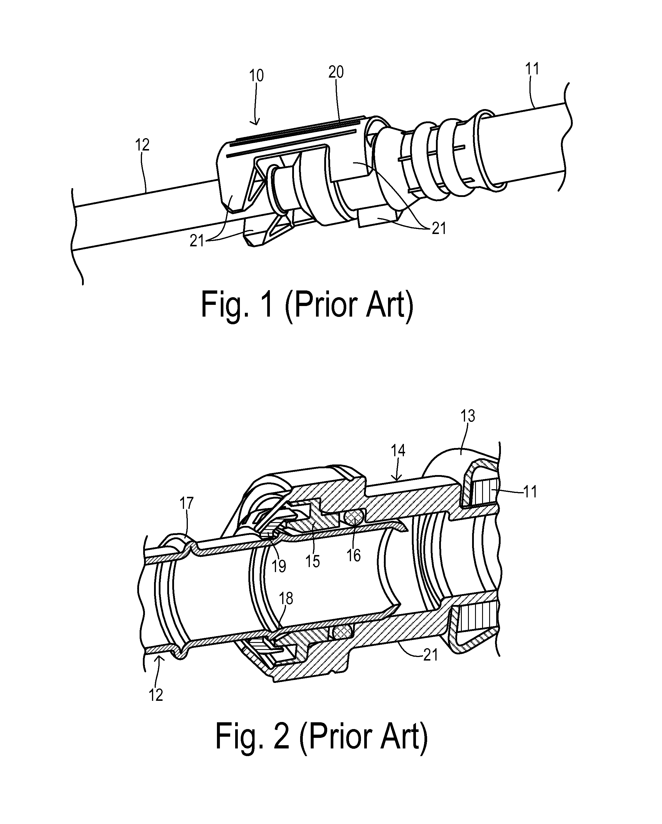
[0023]Referring to FIGS. 1 and 2, a quick connect system 10 interconnects fluid lines 11 and 12. A ferrule 13 helps retain a receiver 14 in a sealed manner within fluid line 11. A plastic insert 15 fits into the end of receiver 14 in order to capture an O-ring seal 16 in a resulting groove. Fluid line 12 is shown as a metal tube having crimp ridges 17 and 18. Plastic insert 15 has an annular snap ring portion 19 that snaps over ridge 18 when line 12 is inserted sufficiently far into receiver 14 that O-ring seal 16 becomes compressed around an outer surface of fluid line 12. A clip 20 has fingers 21 for engaging crimp ridge 17 of line 12 and a groove 21 on receiver 14 to insure a complete and robust coupling of the quick connect. However, the internal snap action may be hard to perceive and the plastic snap components are relatively complex to mold. Furthermore, the use of a separate clip results in added cost and increased difficulty to manufacture.
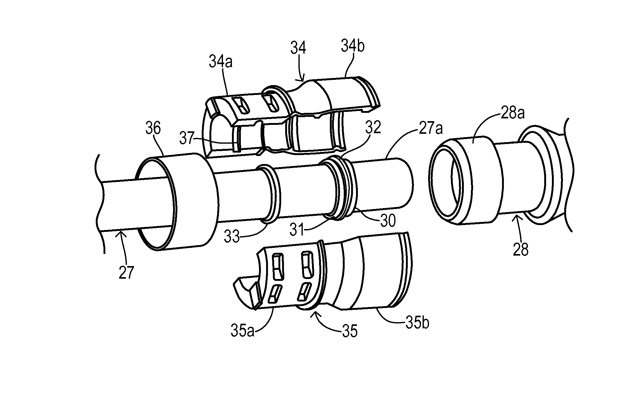
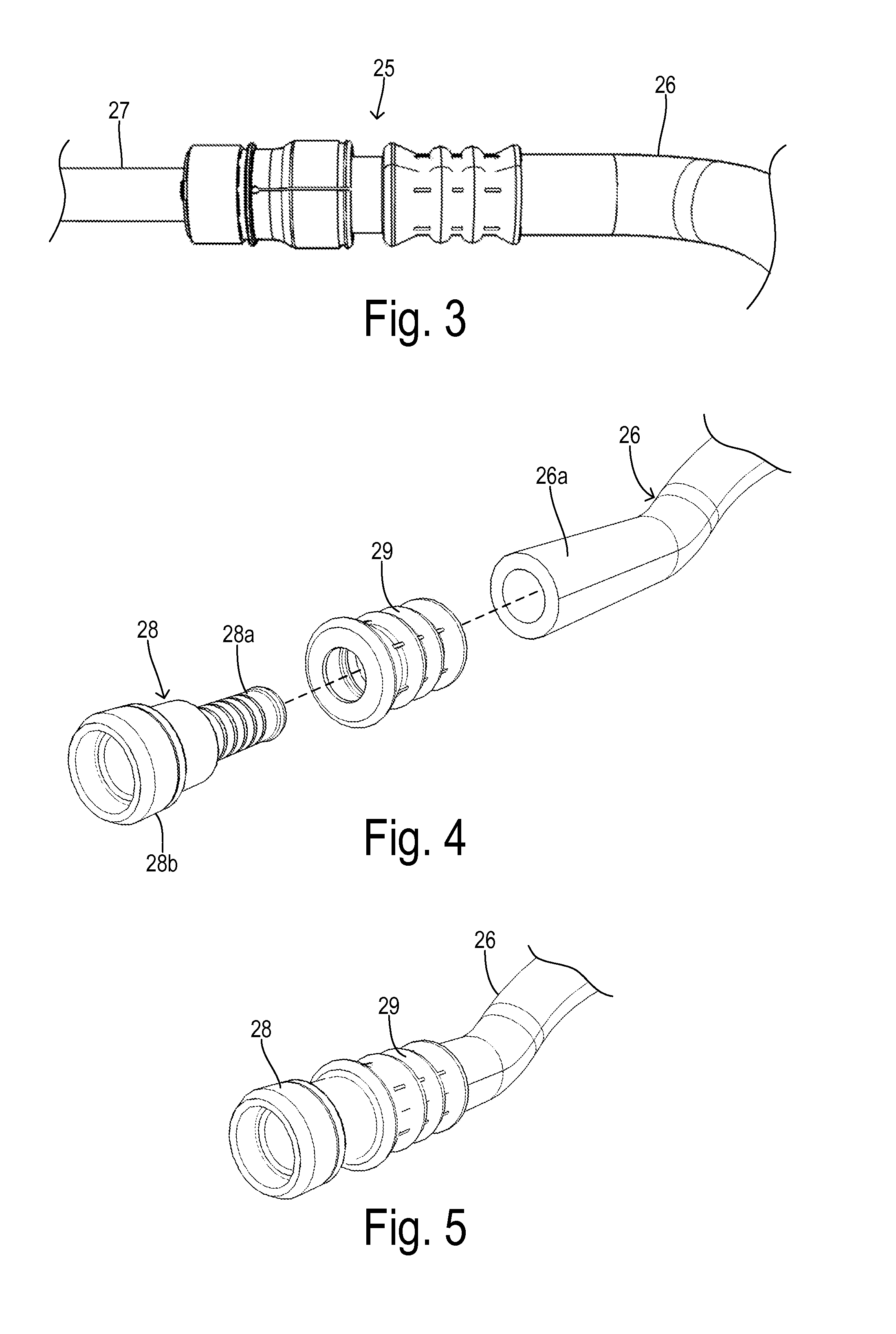
[0024]FIG. 3 shows a quick connect...
PUM
 Abstract
Description
Claims
Application Information
 - R&D
- Intellectual Property
- Life Sciences
- Materials
- Tech Scout
- Unparalleled Data Quality
- Higher Quality Content
- 60% Fewer Hallucinations
Browse by: Latest US Patents, China's latest patents, Technical Efficacy Thesaurus, Application Domain, Technology Topic, Popular Technical Reports.
© 2025 PatSnap. All rights reserved.Legal|Privacy policy|Modern Slavery Act Transparency Statement|Sitemap|About US| Contact US: help@patsnap.com


