
Processor and method for accelerating ray casting

a technology of ray casting and processor, applied in the field of ray casting processing, can solve the problems of user estimation depth, information loss, and excessively long time it takes to read images one by one, and achieve the effect of improving the speed of volume rendering

Active Publication Date: 2016-12-01
CORELINE SOFT
View PDF7 Cites 21 Cited by
  • Summary
  • Abstract
  • Description
  • Claims
  • Application Information

AI Technical Summary

Benefits of technology

The present invention aims to provide a method and apparatus for accelerating ray casting, which can improve the speed of volume rendering. It is designed to improve rendering speed in a GPU, multi-core, or parallel processing environment, by reducing total work time and minimizing work time per block. This technology can be used in a CUDA device, which is a General-Purpose computing on Graphics Processing Units (GPGPU).

Problems solved by technology

Meanwhile, although such a large amount of image information provides useful diagnosis information, it takes an excessively long time and many efforts to read images one by one, as in a conventional method of reading two-dimensional (2D) images.
Meanwhile, since the MIP technique renders a scene while taking into account only the maximum value of density, this scene is characterized in that depth information is lost unlike in a DVR scene, and thus a disadvantage arises in that a user estimates depth while frequently changing an observation direction.
However, although the leaping technique has the advantage of accelerating the generation of a final scene without influencing image quality, it has a disadvantage in which the time required to detect the unnecessary area and the amount of additional memory required to store information about the unnecessary area must be taken into account.
For example, a method for sorting overall data constituting a medical scene in descending order of density values and then starting rendering from the highest value has problems in that a long sorting time is required and the amount of additional memory is large.

Method used


Image

  • Processor and method for accelerating ray casting
  • Processor and method for accelerating ray casting
  • Processor and method for accelerating ray casting

Examples


Embodiment Construction

[0044]Embodiments of the present invention will be described in detail below with reference to the accompanying drawings. In the following description, detailed descriptions of related known components or functions that may unnecessarily make the gist of the present invention obscure will be omitted. Furthermore, in the following description of embodiments of the present invention, specific numerical values are merely examples.

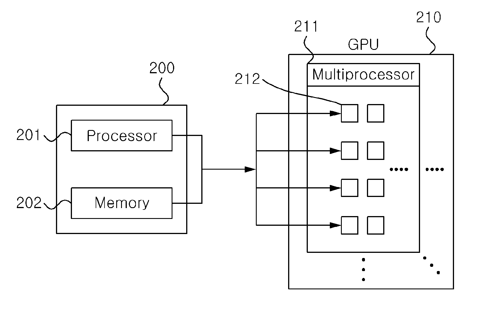
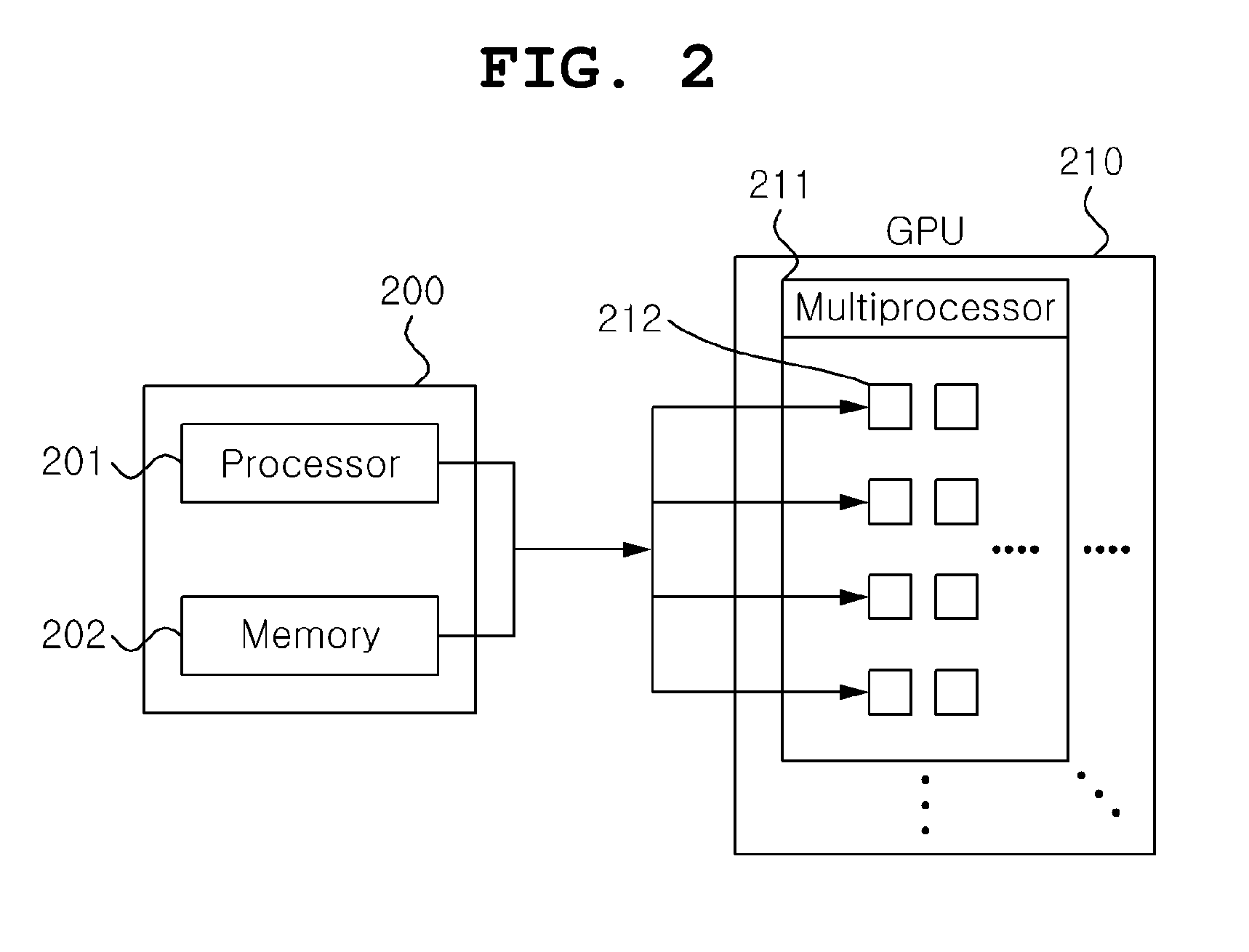
[0045]The present invention relates to a method and apparatus for accelerating ray casting, and more particularly to an accelerating method and apparatus that are capable of improving the speed of rendering using ray casting in a graphics processing unit (GPU), multi-core, or parallel processing environment. First, the overall operation flow of an apparatus 200 for accelerating ray casting according to an embodiment of the present invention is described in brief with reference to FIG. 2.

[0046]FIG. 2 is a conceptual diagram illustrating the overall operation fl...


PUM


Abstract

A processor and method for accelerating ray casting are disclosed herein. The processor for accelerating ray casting includes a computation unit, a sorting unit, an allocation unit, and an execution control unit. The computation unit calculates the length information of a section in which a ray corresponding to each of the pixels of a two-dimensional (2D) scene corresponding to a viewpoint intersects an effective volume in order to apply ray casting to the pixel. The sorting unit sorts the ray based on the length information of the section in which the ray intersects the effective volume. The allocation unit allocates the sorted rays to respective thread groups having a parallel multiprocessor structure in order of the sorting. The execution control unit transfers control instructions to the allocated thread groups so that the allocated thread groups execute ray casting for the sorted rays.

Description

CROSS-REFERENCE TO RELATED APPLICATION[0001]This application claims under 35 U.S.C. §119(a) the benefit of Korean Application No. 10-2015-0076450 filed on May 29, 2015, which is incorporated herein by reference.TECHNICAL FIELD[0002]The present invention relates generally to a method and a processor for accelerating ray casting, and more particularly to a method and a processor for accelerating ray casting, which are capable of improving the speed of volume rendering.BACKGROUND ART[0003]Generally, three-dimensional (3D) medical imaging systems refer to systems for providing medical data as visual information useful for diagnosis using various techniques. In this case, the medical data refers to data that is created by reconstructing information about a bodily organ in a superimposed cross sectional form, obtained through Computerized Tomography (CT) or Magnetic Resonance (MR), into a 3D form.[0004]Recently, with the rapid advance of the technology of medical imaging equipment such as...

Claims


Application Information

Patent Timeline
Patent Type & Authority Applications(United States)
IPC IPC(8): G06T15/06G06T17/20G06T7/00G06T15/08G06T7/60
CPCG06T15/06G06T15/08G06T7/602G06T2210/41G06T17/20G06T2210/52G06T7/0051
Inventor YI, JAEYOUNKIM, JI MINKIM, JIN KOOK
Owner CORELINE SOFT
Learn More