
Unmanned aerial vehicle having a projector and being tracked by a laser tracker

a technology of laser tracker and unmanned aerial vehicle, which is applied in the direction of vehicle position/course/altitude control, process and machine control, instruments, etc., can solve the problems of unstable flight of the unmanned aerial vehicle, insufficient human control, and less than desired accuracy

Inactive Publication Date: 2016-12-01
FARO TECH INC
View PDF28 Cites 88 Cited by
  • Summary
  • Abstract
  • Description
  • Claims
  • Application Information

AI Technical Summary

Benefits of technology

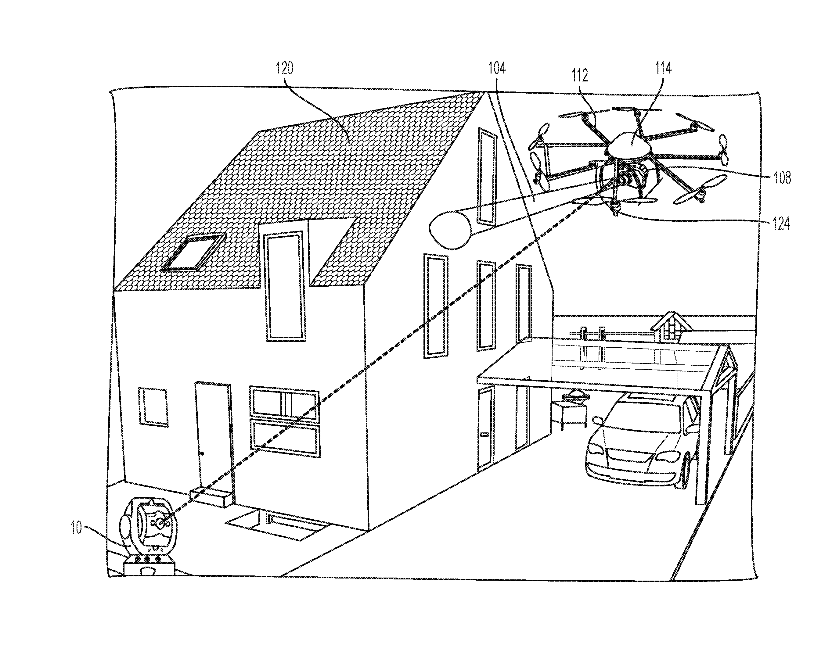
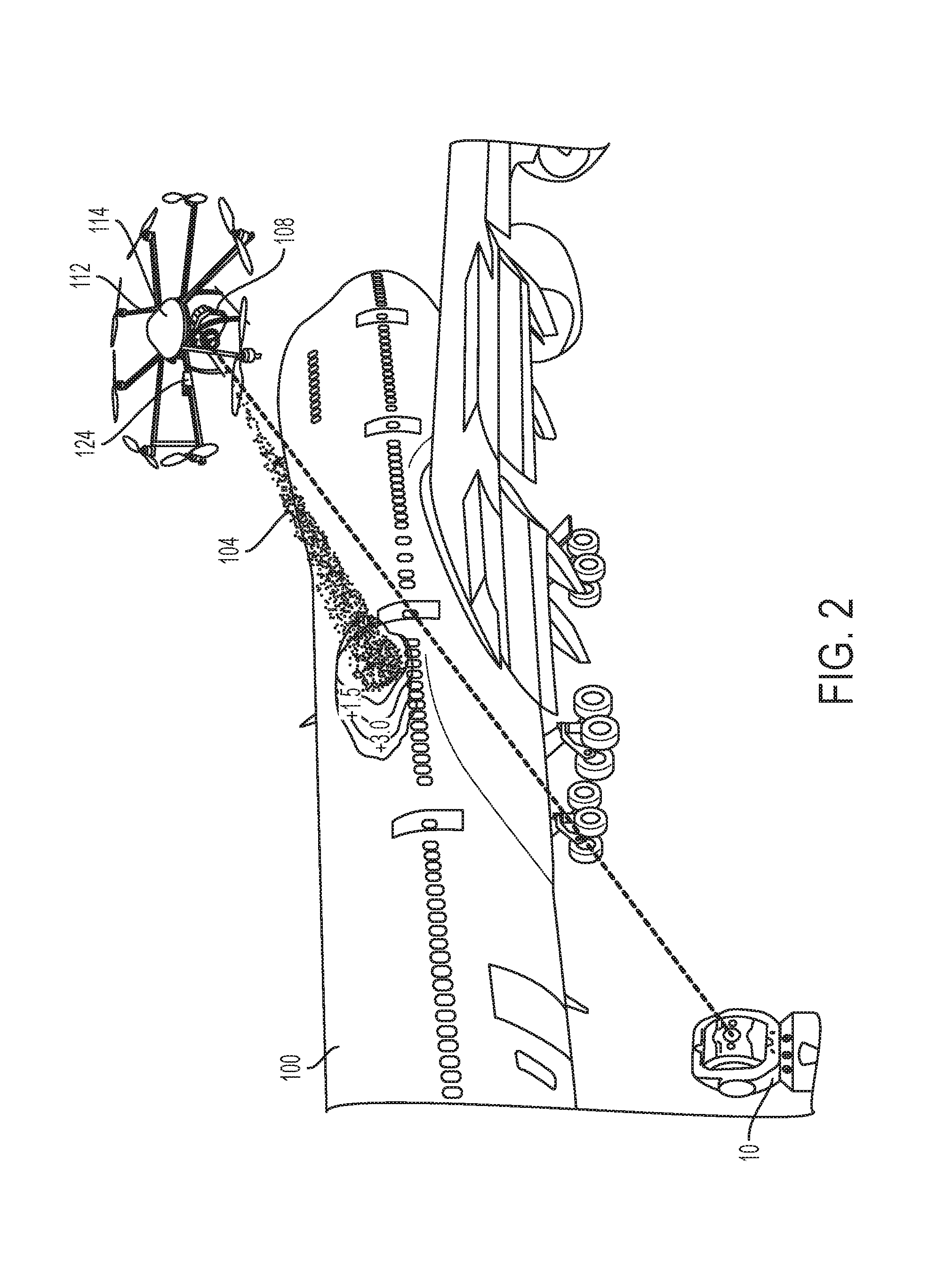
The invention is a system that uses an unmanned aerial vehicle to scan the surface of an object and determine its 3D information. The vehicle then projects information onto the surface using a laser projector. A position tracking device controls the flight path of the vehicle, ensuring accurate navigation. The technical effect of this system is the ability to quickly and accurately capture and project information onto the surface of an object, reducing the need for manual labor and enhancing efficiency.

Problems solved by technology

While this type of UAV flight pattern or path control is suitable for many usages of the UAV (most commonly recreational usages), typically this type of human control is not accurate enough for the situation in which the UAV carries an imaging device (e.g., a 3D laser scanner).
However, controlling the flight path by way of a human-operated remote control most often inherently results in an unstable flight of the UAV, which necessarily leads to the result of incorrect point cloud data capturing and, thus, an incorrect 3D rendering of the object surface.
In addition, an unstable flight of the UAV also results in a less than desired accuracy in the projection of information onto an object by a projector that is carried by the UAV.
This is because unstable UAV flight (e.g., rapid “jerking” UAV motion, UAV movement when hovering instead is desired, etc.) results in unstable positioning of the projector.
The unstable UAV flight may result in an inability of a human on the ground or an imaging device on the UAV to properly read or view the projected information.

Method used


Image

  • Unmanned aerial vehicle having a projector and being tracked by a laser tracker
  • Unmanned aerial vehicle having a projector and being tracked by a laser tracker
  • Unmanned aerial vehicle having a projector and being tracked by a laser tracker

Examples


Embodiment Construction

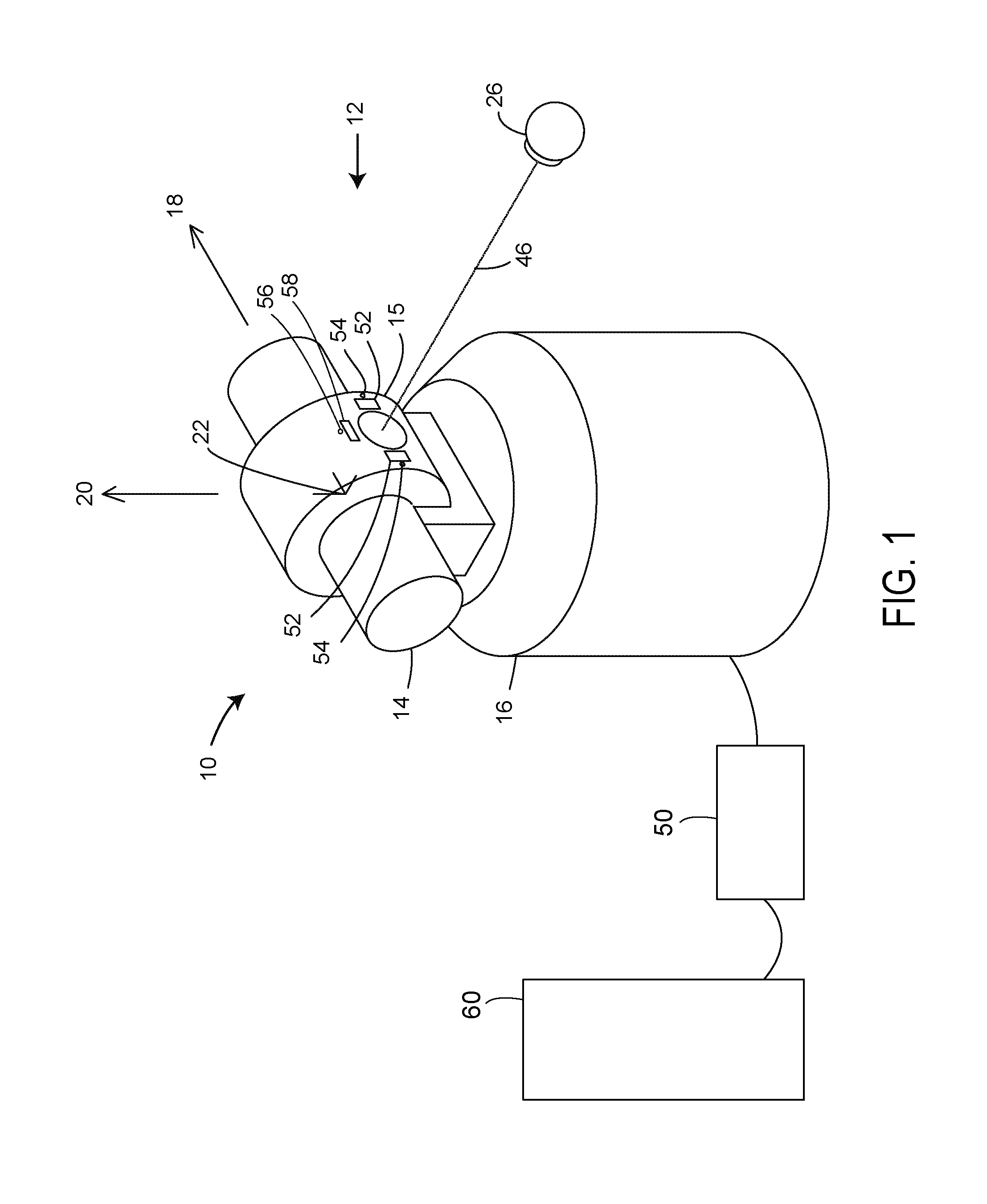
[0025]An exemplary laser tracker 10 is illustrated in FIG. 1. An exemplary gimbaled beam-steering mechanism 12 of laser tracker 10 includes zenith carriage 14 mounted on azimuth base 16 and rotated about azimuth axis 20. Payload 15 is mounted on zenith carriage 14 and rotated about zenith axis 18. Zenith mechanical rotation axis 18 and azimuth mechanical rotation axis 20 intersect orthogonally, internally to tracker 10, at gimbal point 22, which is typically the origin for distance measurements. Laser light beam 46 virtually passes through gimbal point 22 and is pointed orthogonal to zenith axis 18. In other words, laser beam 46 is in a plane normal to zenith axis 18. Laser beam 46 is pointed in the desired direction by motors within the tracker 10 that rotate payload 15 about zenith axis 18 and azimuth axis 20. Zenith and azimuth angular encoders, internal to the tracker 10, are attached to zenith mechanical axis 18 and azimuth mechanical axis 20 and indicate, to relatively high ac...


PUM


Abstract

An unmanned aerial vehicle (UAV) such as a drone, quadcopter or octocopter having a projector on board for projecting information into physical space such as onto objects or locations while the UAV is in flight, and further with the position and orientation (i.e., the six degrees of freedom) of the UAV in flight being accurately tracked and controlled from the ground, e.g., by a laser tracker or a camera bar, thereby leading to a relatively more stable flight of the UAV.

Description

CROSS REFERENCE TO RELATED APPLICATIONS[0001]This application claims the benefit of U.S. Provisional Application Ser. No. 62 / 167,978, filed May 29, 2015, the entire disclosure of which is incorporated herein by reference.FIELD OF THE INVENTION[0002]The present disclosure relates in general to unmanned aerial vehicles (UAVs), and more particularly to a UAV such as a drone, quadcopter or octocopter having a projector on board for projecting information into physical space such as onto objects or terrain locations while the UAV is in flight, and further with the position and orientation of the UAV in flight being accurately tracked and controlled from the ground, e.g., by a laser tracker or a camera bar.BACKGROUND OF THE INVENTION[0003]Unmanned aerial vehicles (UAVs) such as drones, quadcopters or octocopters are rapidly becoming increasingly popular for use in both business and recreational activities and for various different purposes. These UAVs are relatively inexpensive, are easy ...

Claims


Application Information

Patent Timeline
IPC IPC(8): G05D1/00B64D47/08G05D1/10B64C39/02
CPCG05D1/0011B64C39/024B64D47/08B64C2201/108G05D1/101B64C2201/123G05D1/0094G05D1/102B64U10/13B64U2101/30
Inventor GRAU, MARKUS
Owner FARO TECH INC
Learn More