
Spring mechanism and linear motion displacement mechanism

Active Publication Date: 2016-12-01
HONDA MOTOR CO LTD
View PDF6 Cites 6 Cited by
  • Summary
  • Abstract
  • Description
  • Claims
  • Application Information

AI Technical Summary

Benefits of technology

The present invention provides a spring mechanism and a linear motion displacement mechanism that can deform a transducer with high symmetry and structure in a small size. This helps in creating a compact and efficient technology.

Problems solved by technology

Because of this, particularly if the elastic deformation of the elastic deformation part of the transducer becomes an imbalanced deformation (elastic deformation having low symmetry of elastic deformation shape), during the elastic deformation in which the displacement in the central part of the elastic deformation part becomes comparatively large, a damage such as a crack of the elastic deformation part due to local stress concentration tends to easily occur.
Consequently, the size of the spring mechanism results in being enlarged.
However, in this case, the rod results in appearing from and disappearing into the housing on both sides (both sides in the thickness direction of the elastic deformation part) of the housing, and accordingly a space necessary for the arrangement of the spring mechanism results in being large.

Method used


Image

  • Spring mechanism and linear motion displacement mechanism
  • Spring mechanism and linear motion displacement mechanism
  • Spring mechanism and linear motion displacement mechanism

Examples


Embodiment Construction

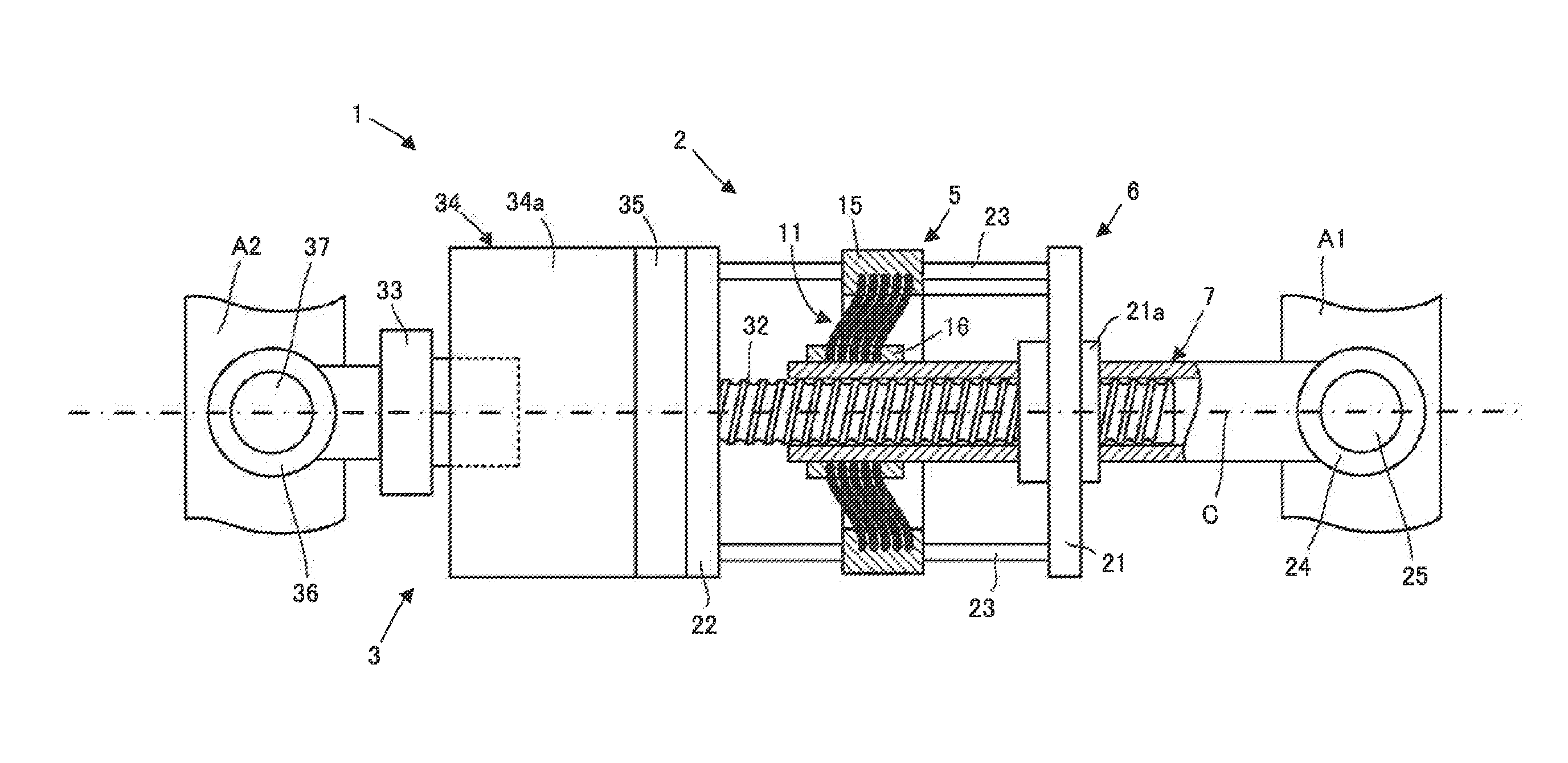
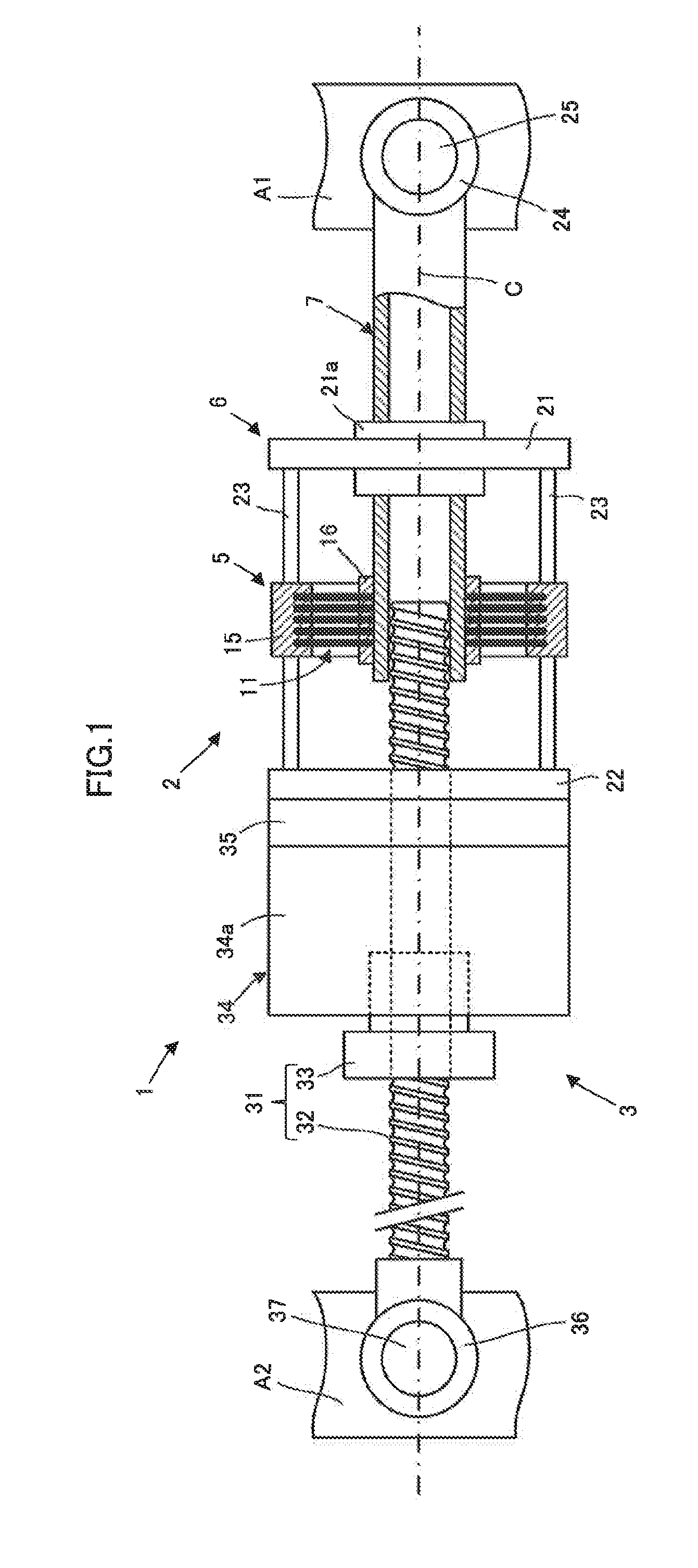
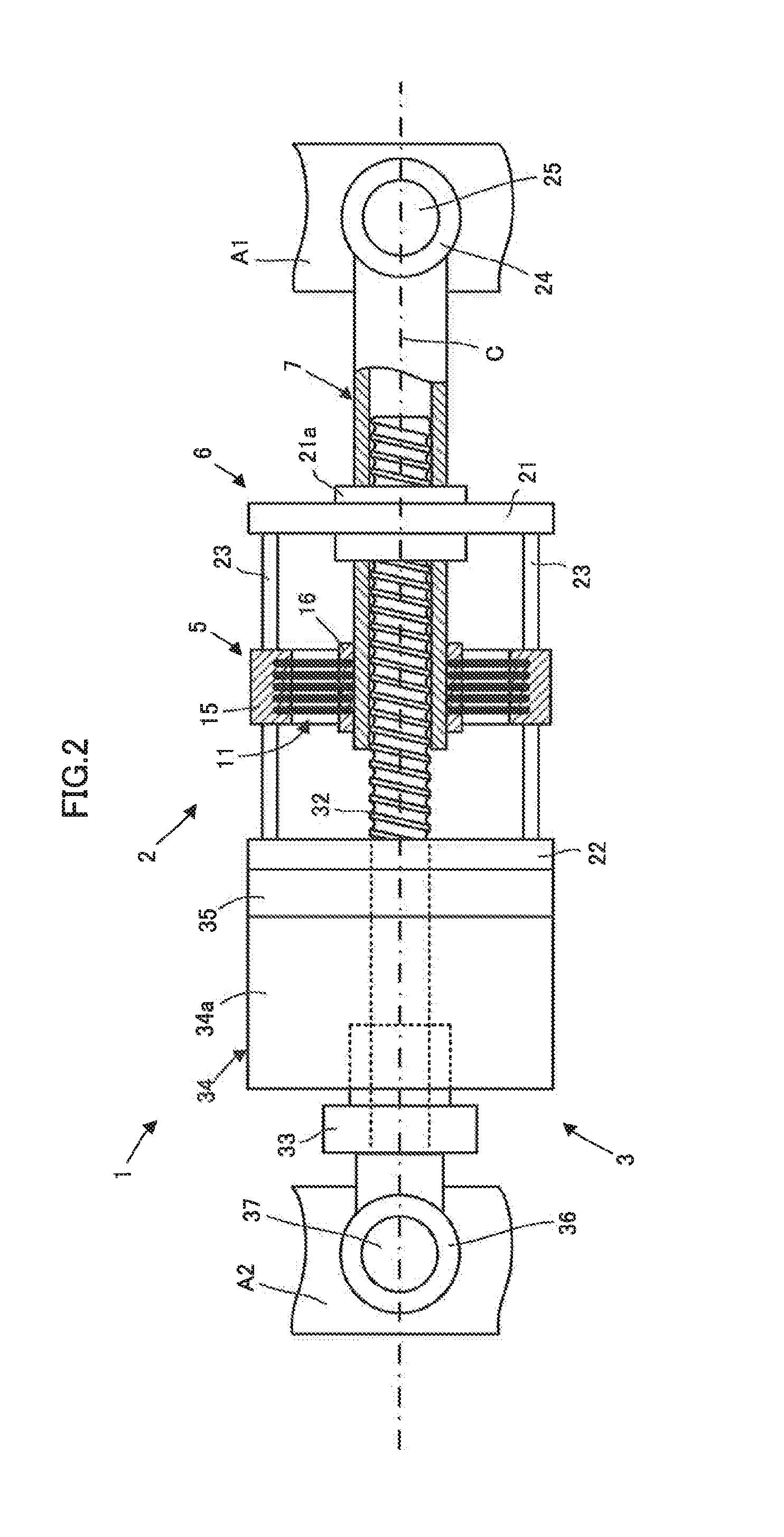
[0051]One embodiment of the present invention will be described below with reference to FIG. 1 to FIG. 4. With reference to FIG. 1, a linear motion displacement mechanism 1 of the present embodiment is a mechanism which carries out relative displacement between a first member A1 and a second member A2. More specifically, the linear motion displacement mechanism 1 carries out the relative displacement between the first member A1 and the second member A2 so that a connecting portion of the first member A1 and a connecting portion of the second member A2 move close to or move away from each other along a line which connects the connecting portions. The first member A1 and the second member A2 may also be an arbitrary member.

[0052]As one example, for instance, two links of a robot can be adopted as the first member A1 and the second member A2. In this case, the linear motion displacement mechanism 1 can be used as a mechanism which drives a rotary type joint that connects the first memb...


PUM


Abstract

The present invention provides a spring mechanism which can elastically deform an elastic deformation part with a film shape of a transducer into a shape having high symmetry, and also can be structured in a small size. A spring mechanism 2 includes: a cylindrical member 7 that is provided so as to extend toward a first element member 21 from an elastic deformation part 11 of a transducer 5, and also is arranged so as to slidably penetrate the first element member 21 in the direction of a central axis line C of the elastic deformation part 11; and a rod member 32 that is provided so as to extend toward the cylindrical member 7 from a second element member 22 side, and is slidably inserted in the cylindrical member 7 in the direction of the central axis line C of the elastic deformation part 11.

Description

BACKGROUND OF THE INVENTION[0001]Field of the Invention[0002]The present invention relates to a spring mechanism that includes a transducer that has an elastic deformation part with a film shape, which elastically extends and contracts in a direction along a face, depending on input energy, and to a linear motion displacement mechanism which has the spring mechanism.[0003]Description of the Related Art[0004]Conventionally, a mechanism is known that is described, for instance, in FIG. 6 to FIG. 8 of Japanese Patent Laid-Open No. 2009-41463, as a mechanism corresponding to the spring mechanism which includes the transducer that has the elastic deformation part with the film shape, which elastically extends and contracts in the direction along the face, depending on.[0005]The spring mechanism described in the above described Japanese Patent Laid-Open No. 2009-41463 includes: an electrostrictive element as the transducer, which has the elastic deformation part that includes an elastic f...

Claims


Application Information

Patent Timeline
IPC IPC(8): F16H25/20F16M13/02
CPCF16M13/022F16H25/20F16F1/32F16F3/02F16F15/005F16F1/021H10N30/00
Inventor ORITA, ATSUO
Owner HONDA MOTOR CO LTD
Learn More