
Laser spark plug having an improved seal between the combustion chamber window and the casing

a laser and casing technology, applied in the direction of sparking plugs, engine components, electrical appliances, etc., can solve the problems of unwanted reduction of axial preloading force, and achieve the effect of improving the casing

Inactive Publication Date: 2016-11-24
ROBERT BOSCH GMBH
View PDF10 Cites 3 Cited by
  • Summary
  • Abstract
  • Description
  • Claims
  • Application Information

AI Technical Summary

Benefits of technology

[0005]Accordingly, an object of the present invention is to further improve a casing for a laser spark plug, in order to provide an imperviousness of the casing, and therefore a service life of a laser spark plug having the casing, that is even further increased in comparison with the related art, without necessarily having to provide, for this, a continuous material connection that is complicated from the standpoint of production engineering.
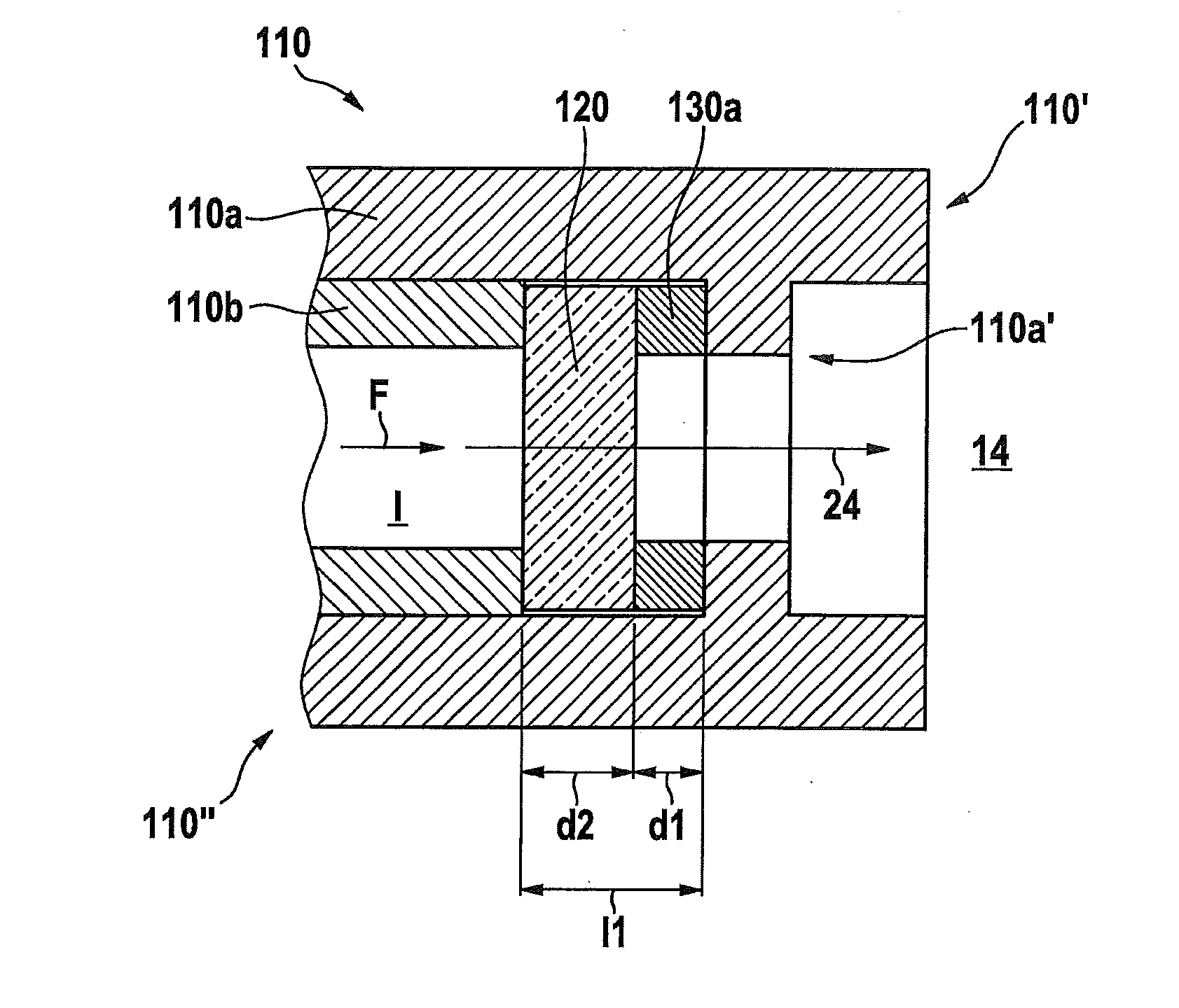
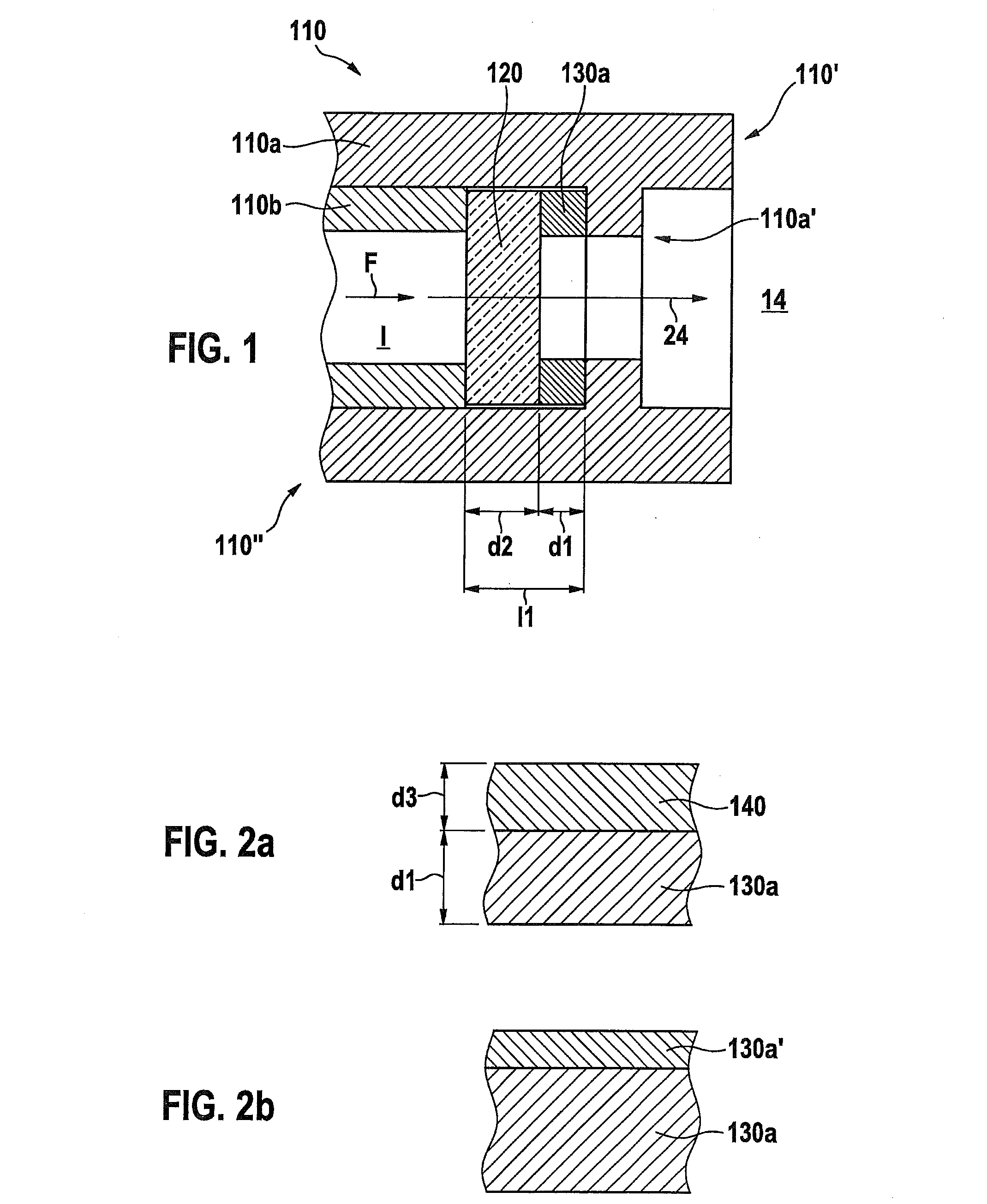
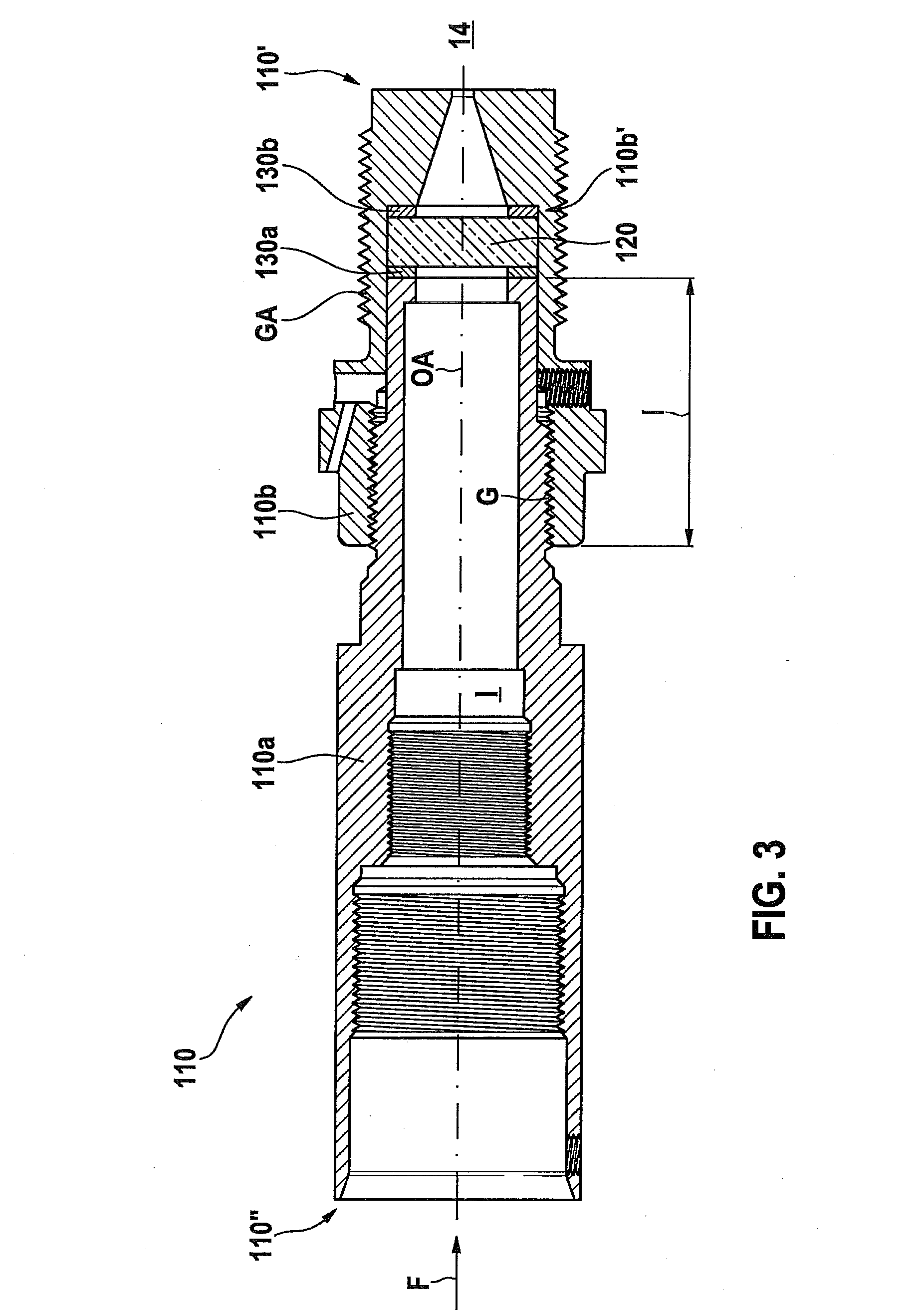
[0008]Therefore, when the casing is heated up to the operating temperature of the laser spark plug, the inner axial dimension of the spatial region increases relatively steeply, while an axial longitudinal expansion of the combustion chamber window essentially parallel to this is relatively low, which means that an unwanted reduction in the axial preloading force is generated. Due to the selection of the present invention of the thermal expansion coefficient for the sealing element also situated in the spatial region, because of its relatively large linear thermal expansion in the axial direction, which is greater than that of the first casing part, the sealing element offsets the relatively low linear thermal expansion of the combustion chamber window at least partially or compensates for it almost completely, which means that the preloading force necessary for the sealing action is essentially maintained even in the event of large temperature fluctuations.
[0014]In a further advantageous specific embodiment, it is provided that a thickness of the sealing element be between approximately 0.4 mm (millimeters) and approximately 3 mm, in particular, approximately 1.0 mm; particularly effective sealing action and particularly efficient compensation for the thermal expansion of the materials of the casing part and the combustion chamber window being simultaneously obtained. In particular, two sealing elements, in particular, sealing rings, may be provided, which are each approximately 1 mm thick and may be positioned in such a manner, that they form a layer construction, in the middle of which the combustion chamber window is situated. This dimensioning is particularly favorable in the case of a combustion chamber window having a thickness of approximately 4 mm.
[0017]In a further advantageous specific embodiment, the coating is made of, in particular, one copper layer per coating side, of a thickness between approximately 50 μm and approximately 150 μm, which may be, approximately 100 μm. According to tests of the Applicant, such a copper coating may be advantageously provided as a “filler,” that is to say, as an actual sealing material, which may, advantageously, further level out the surface roughness of the components including the coating (casing part, combustion chamber window), in that the material of the sealing element or its coating spreads itself out into these contact surfaces of the components involved, for example, by creep, during the bracing or compressing at a specifiable preloading force. In a further advantageous specific embodiment, the flatness of the coating is, advantageously, approximately 2 μm or better.
[0020]In one further advantageous specific embodiment, it is provided that in a region of contact with the at least one casing part and / or with the combustion chamber window, the sealing element have a lapped surface, through which further increased sealing action is provided.

Problems solved by technology

Therefore, when the casing is heated up to the operating temperature of the laser spark plug, the inner axial dimension of the spatial region increases relatively steeply, while an axial longitudinal expansion of the combustion chamber window essentially parallel to this is relatively low, which means that an unwanted reduction in the axial preloading force is generated.

Method used


Image

  • Laser spark plug having an improved seal between the combustion chamber window and the casing
  • Laser spark plug having an improved seal between the combustion chamber window and the casing
  • Laser spark plug having an improved seal between the combustion chamber window and the casing

Examples


Embodiment Construction

[0031]In FIG. 6, an internal combustion engine is designated, on the whole, by reference numeral 10. It may be used for propelling a motor vehicle not shown. Internal combustion engine 10 usually includes several cylinders, only one of which is denoted in FIG. 5 by the reference numeral 12. A combustion chamber 14 of cylinder 12 is delimited by a piston 16. Fuel reaches combustion chamber 14 directly through an injector 18, which is connected to a fuel pressure reservoir 20 that is also referred to as a rail. Alternatively, the fuel-air mixture may also be formed outside of the combustion chamber, for example, in the intake manifold or, in the case of stationary engines, in front of the turbocharger as well.

[0032]The fuel-air mixture 22 present in combustion chamber 14 is ignited by a laser pulse 24, which is radiated into combustion chamber 14, in this instance, onto ignition point ZP, by an ignition device 27 that includes an ignition laser 26. To this end, laser device 26 is supp...


PUM


Abstract

A casing for a laser spark plug, in particular, of an internal combustion engine of a motor vehicle, or of a stationary engine; the casing including at least one casing part and a combustion chamber window joined to the casing part to form a seal at least regionally; characterized in that at least one sealing element, whose coefficient of thermal expansion at an operating temperature of the laser spark plug is greater than the coefficient of thermal expansion of the casing part at the operating temperature of the laser spark plug, is provided between the casing part and the combustion chamber window.

Description

FIELD OF THE INVENTION[0001]The present invention relates to a casing for a laser spark plug, in particular, of an internal combustion engine of a motor vehicle, or of a stationary engine; the casing including at least one casing part and a combustion chamber window joined to the casing part in a sealing manner in at least some areas.BACKGROUND INFORMATION[0002]German patent document DE 10 2007 041 528 A1 discusses a laser ignition device or laser spark plug for an internal combustion engine, including a laser-active solid body, a combustion chamber window and a casing, where the casing and the combustion chamber window are interconnected in a continuous material manner at least indirectly to seal off the interior chamber from the combustion chamber.[0003]At one end of the casing facing the combustion chamber, there is a so-called combustion chamber window, which is able to transmit the laser beams generated in the ignition laser. This combustion chamber window must be accommodated ...

Claims


Application Information

Patent Timeline
Patent Type & Authority Applications(United States)
IPC IPC(8): H01T13/06H01T14/00F02P23/04
CPCH01T13/06H01T14/00F02P23/04
Inventor ENGELHARDT, JOERGWOLZ, DIETERRAIMANN, JUERGENWOERNER, PASCALWEINROTTER, MARTIN
Owner ROBERT BOSCH GMBH
Learn More