
Smart box for automatic feature testing of smart phones and other devices

a smart phone and feature testing technology, applied in the direction of receiving monitoring, programme control, instruments, etc., can solve the problems of not being able to perform a complete hardware and software test on the phone and to test all the functions on the phone automatically, affecting the quality of the product, and affecting the service life of the customer, so as to achieve the effect of reducing the subjectivity of manual testing and shortening the tim

Active Publication Date: 2016-11-17
ADVANTEST AMERICA
View PDF11 Cites 46 Cited by
  • Summary
  • Abstract
  • Description
  • Claims
  • Application Information

AI Technical Summary

Benefits of technology

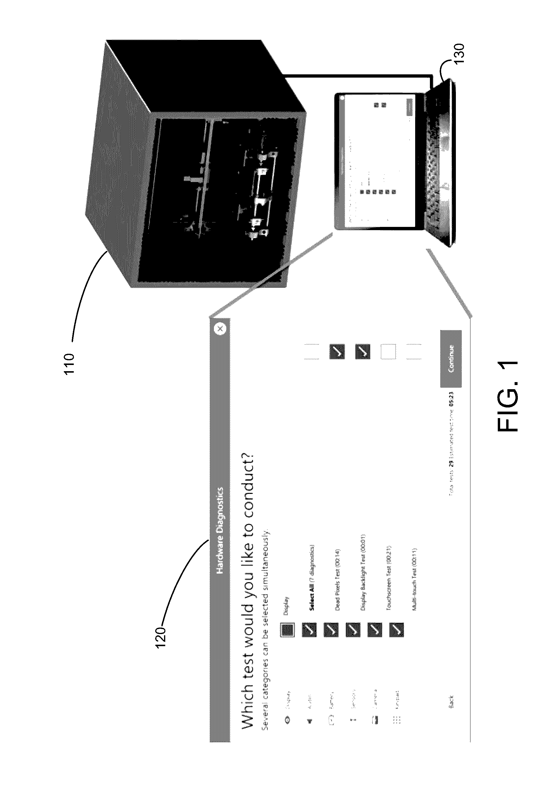
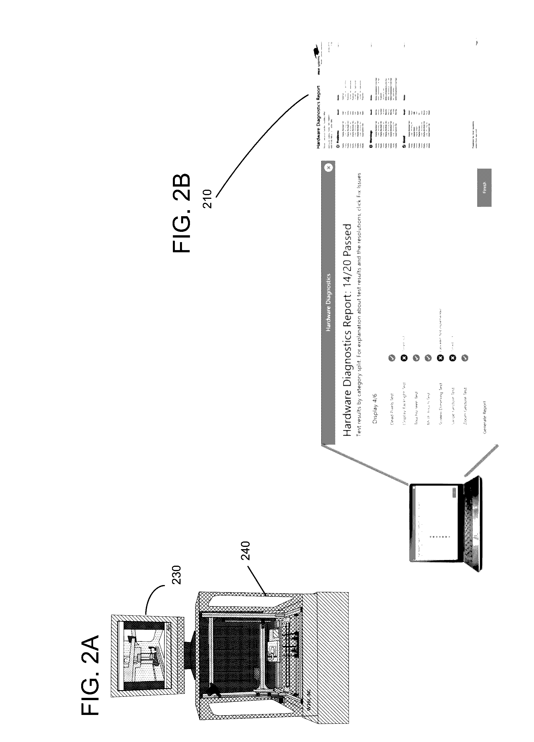
[0013]Embodiments of the present invention provide a tester system (hereinafter referred to as the “Smart Box”) that allows a user to perform a series of hardware and software tests in a closed and controlled environment, thus eliminating subjectivity of manual testing. Embodiments of the present invention are also optimized for speed and configured to test the major features of the phone in a short duration of time. Further, embodiments of the present invention transmit all test data to a centralized server enabling mobile operators to track feature issues, model issues, geographic and / or store issues. Accordingly, embodiments of the present invention are enabled for global analytics.
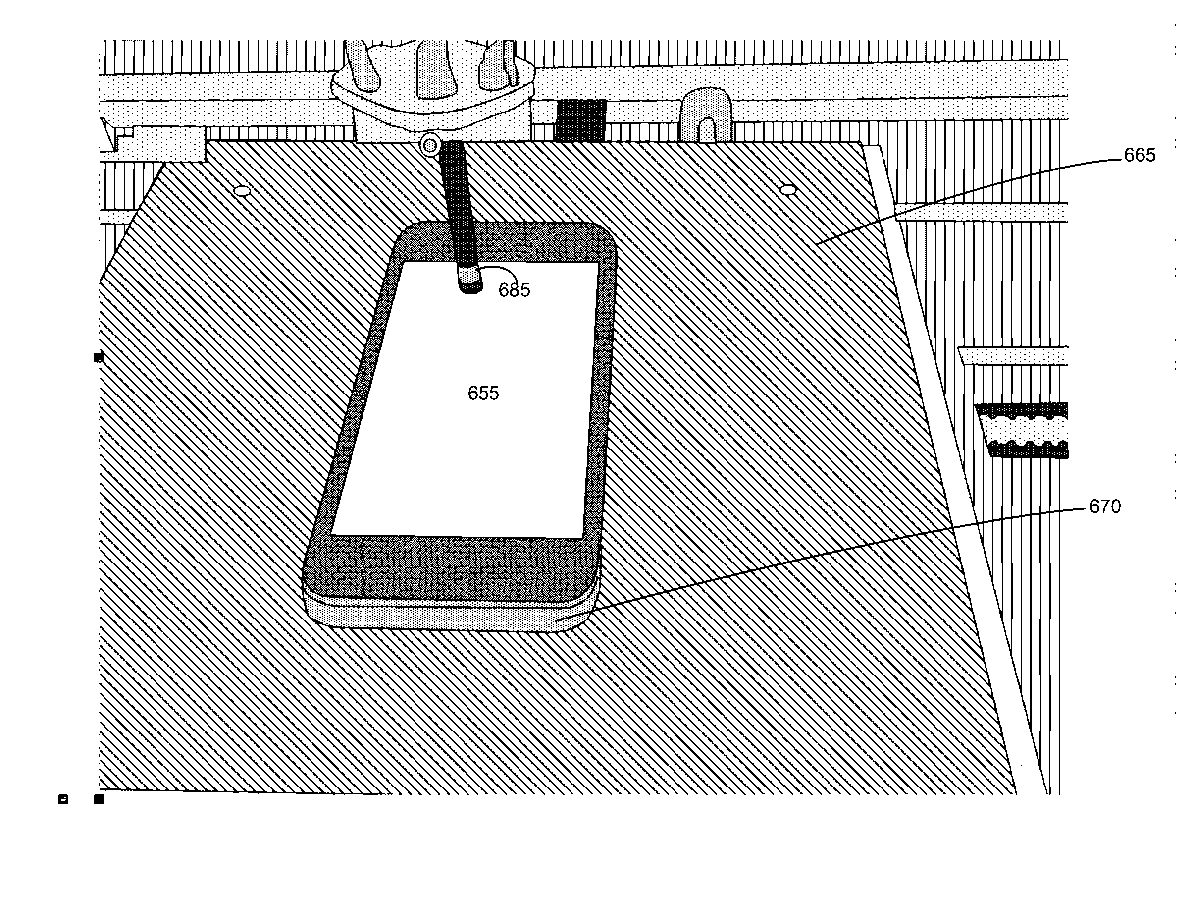
[0014]In one embodiment, the Smart Box is a box-shaped apparatus comprising robotics that allows the smart device to be moved in the x, y and z directions. Further, the apparatus comprises a stylus that can also move in the x, y and z directions and be used to actuate buttons on the smart device. In one embodiment of the present invention the smart device moves in the x and y direction while the stylus moves in the z direction. Accordingly, embodiments of the present invention are configured to allow the stylus and mobile device the mobility so that the stylus can make contact with the device at any location on the device to interface therewith.

Problems solved by technology

Some retail facilities have the capability of performing some basic software testing of the phone, however, no retail facility has the ability to perform a complete hardware and software test on the phone and to test all the functions on the phone automatically.
Accordingly, the phone either needs to be returned and replaced, which over time can result in substantial costs to the manufacturer.
Alternatively, if the phone cannot be returned or replaced for any reason, the customer ends up dissatisfied if the problems with the phone are not easily diagnosed and fixed.
In some cases, the problem with the phone cannot be diagnosed at the retail facility.
Currently, even the repair centers do not have a satisfactory solution to automatically test all the hardware and software functions on a smart phone.
Further, even if the device is repaired, there is no traceability for the repair work performed or any fully automated method for verifying that the repair work was performed satisfactorily.
Accordingly, the repair and test methodologies currently in place are subjective and not foolproof.
Any errors in the repair or verification process will cost the manufacturers more money and result in customer dissatisfaction.
Further, sending the phone to a repair center will almost always leave a customer dissatisfied as most customers cannot afford to be without their smart device for an extended period of time.
Additionally, the production facilities at which the phones are manufactured also do not currently have any mechanisms in place for complete hardware and software automated testing of the phone devices.
Most of the functional testing that takes place before the phones are packaged is manual and, accordingly, it is error-prone and expensive.
Further, the cost and susceptibility to error of the manual test processes currently in place is increasing as the feature-set on the devices increases.

Method used


Image

  • Smart box for automatic feature testing of smart phones and other devices
  • Smart box for automatic feature testing of smart phones and other devices
  • Smart box for automatic feature testing of smart phones and other devices

Examples


Embodiment Construction

[0062]Reference will now be made in detail to embodiments, examples of which are illustrated in the accompanying drawings. While the embodiments will be described in conjunction with the drawings, it will be understood that they are not intended to limit the embodiments. On the contrary, the embodiments are intended to cover alternatives, modifications and equivalents. Furthermore, in the following detailed description, numerous specific details are set forth in order to provide a thorough understanding. However, it will be recognized by one of ordinary skill in the art that the embodiments may be practiced without these specific details. In other instances, well-known methods, procedures, components, and circuits have not been described in detail as not to unnecessarily obscure aspects of the embodiments.

Notation and Nomenclature Section

[0063]Some regions of the detailed descriptions which follow are presented in terms of procedures, logic blocks, processing and other symbolic repr...


PUM


Abstract

An automatic system level testing (ASLT) system for testing smart devices is disclosed. The system comprises a system controller operable to be coupled with a smart device in an enclosure, wherein the system controller comprises a memory comprising test logic and a processor. The system also comprises the enclosure, wherein the enclosure comprises a plurality of components, the plurality of components comprising: (i) a robotic arm comprising a stylus, wherein the stylus is operable to manipulate the smart device to simulate human interaction therewith; and (ii) a platform comprising a device holder, wherein the device holder is operable to receive a smart device inserted there into. The processor is configured to automatically control the smart device and the plurality of components in accordance with the test logic.

Description

CROSS-REFERENCE TO RELATED PATENTS AND APPLICATIONS[0001]This application claims priority from U.S. Provisional Application No. 62 / 088,319, Attorney Docket W2BI-003-00.00US, filed Dec. 5, 2014, the entire disclosure of which is incorporated herein by reference.[0002]The present application is related to U.S. Pat. No. 8,737,980, filed Sep. 27, 2012, entitled “End to end Application Automatic Testing,” naming Dinesh Doshi, Artun Kutchuk, Deepa Jagannatha, and Ramesh Parmar as inventors. This patent is incorporated herein by reference in its entirety and for all purposes.[0003]The present application is related to U.S. patent application Ser. No. ______, filed ______, entitled “SMART BOX FOR AUTOMATIC FEATURE TESTING OF SMART PHONES AND OTHER DEVICES,” naming Derek Diperna, Ira Leventhal, Keith Schaub and Artun Kutchuk as inventors, and having attorney docket number W2BI-0003-01U00US. That application is incorporated herein by reference in its entirety and for all purposes.[0004]The pr...

Claims


Application Information

Patent Timeline
Patent Type & Authority Applications(United States)
IPC IPC(8): H04B17/16B25J9/16H04B17/11H04B17/29H04B17/21H04W4/02H04W4/80
CPCH04B17/16H04B17/29B25J9/1679H04B17/11H04B17/21G06F11/2221H04W24/06G05B2219/40041G05B2219/45089G05B2219/37021H04W4/80H04M1/24H04W84/12H02J7/0044H04W4/02H02J7/0048G05B19/41875G05B2219/37022G05B2219/37231G05B2219/37388G05B2219/37433G05B2219/37634G05B2219/37431G05B2219/37368G05B2219/32368G06F3/0346H04M1/04H04N7/18H04W24/02
Inventor DIPERNA, DEREKLEVENTHAL, IRASCHAUB, KEITHKUTCHUK, ARTUN
Owner ADVANTEST AMERICA
Learn More