
A Network Distributed Dynamic Equalized Power Supply Method (as amended)

Active Publication Date: 2016-11-17
GCCALLIANCE
View PDF2 Cites 0 Cited by
  • Summary
  • Abstract
  • Description
  • Claims
  • Application Information

AI Technical Summary

Benefits of technology

The technology plan described in this patent aims to improve the reliability and flexibility of power supply. This means that the risk of power supply failure is reduced, and the power supply can be shared among multiple devices to increase energy utilization and reduce energy consumption.

Problems solved by technology

In the current time, most IT equipment, data center, and facility room adopt the traditional Alternative Current (AC) Uninterruptible Power Supply (UPS) centralized power supply method, and the traditional UPS system adopts the double conversion, Alternative Current (AC) to Direct Current (DC) to Alternative Current (AC), to supply power to the IT equipment, which needs 2 times of conversion processes, and the traditional UPS system adopts the power management method with single measure, and could not flexibly and dynamically distribute the power as per the different electricity consumption status of each different equipment, which causes the waste of electricity.
In addition, the safety and reliability of the power management method of the traditional UPS system are poor in case of any fault incurred of UPS, which the power supply of the entire data center will be impacted due to power supply incident and result in the service outage of data center.
Therefore, the current technology is imperfect and has defect, which needs to be improved.

Method used


Image

  • A Network Distributed Dynamic Equalized Power Supply Method (as amended)
  • A Network Distributed Dynamic Equalized Power Supply Method (as amended)

Examples


Embodiment Construction

[0022]In the below, together with the drawing and specific embodiments, this invention is detailed described.

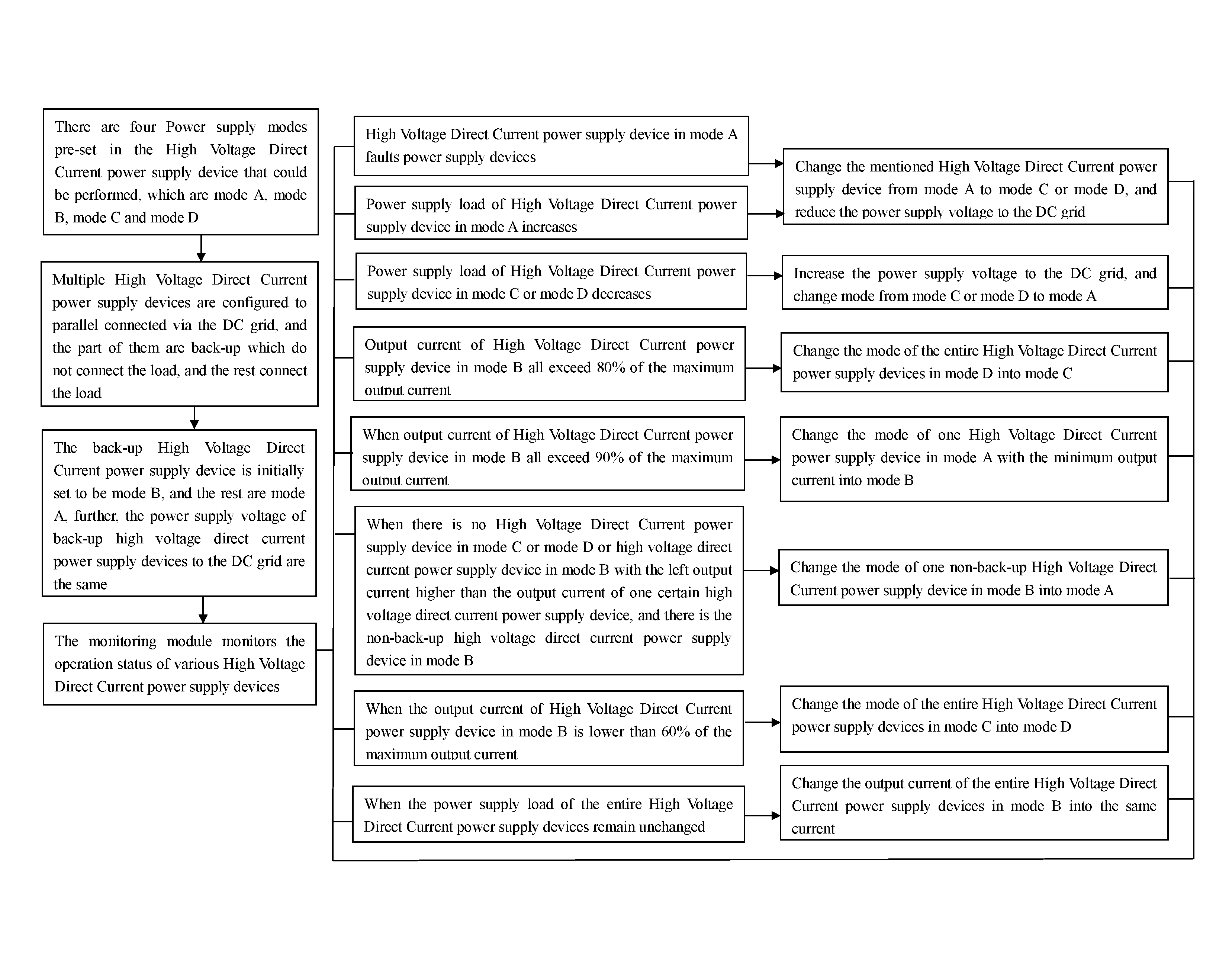
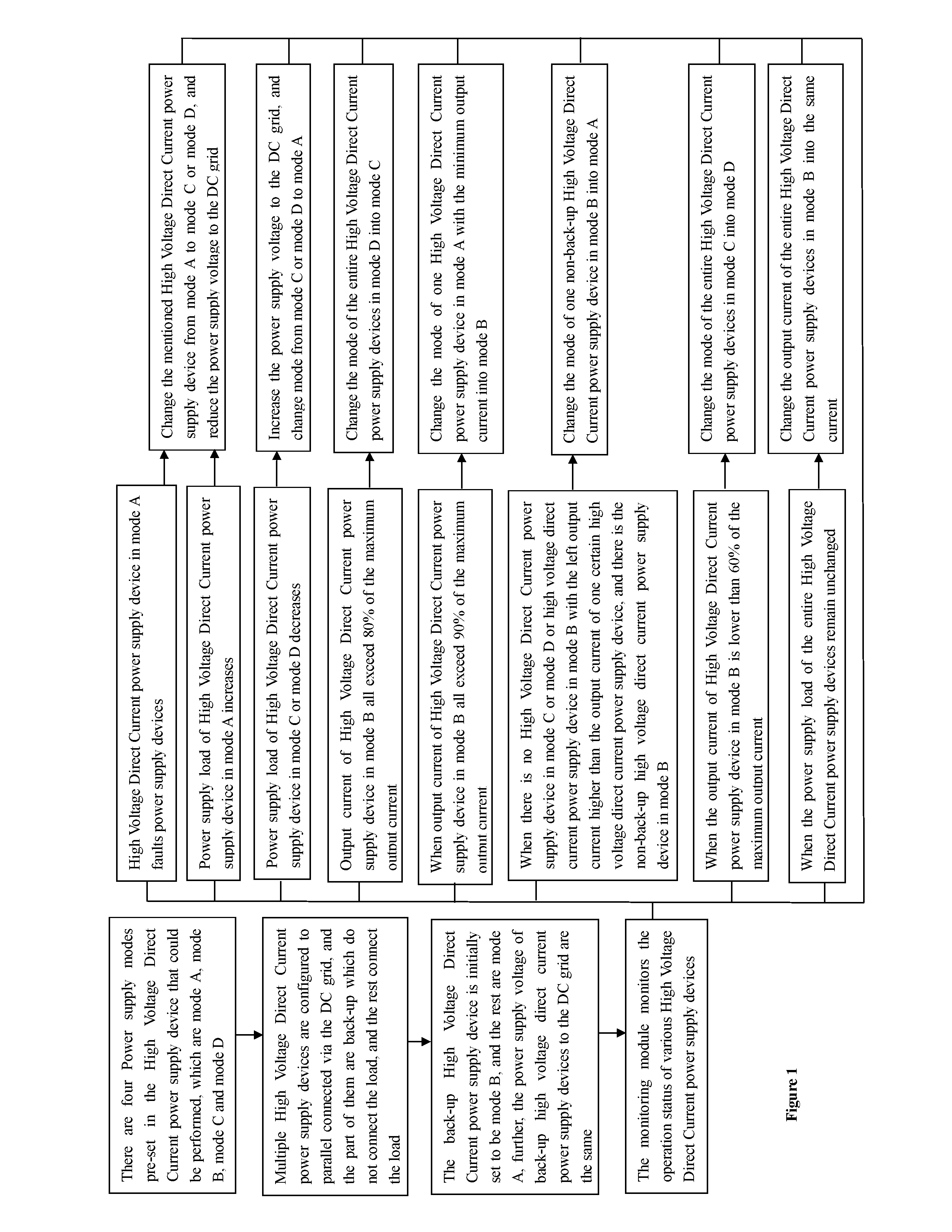
[0023]As shown in FIG. 1, this invention is a Network Distributed Dynamic Equalized Power Supply Method, which adopts multiple High Voltage Direct Current power supply devices to supply power to different loads, in the meantime, the entire High Voltage Direct Current power supply devices form the networked power supply state that mutually supporting to supply power by connecting with DC Grid. During the usage, the quantity of High Voltage Direct Current power supply device shall be provided as per the quantity of equipments in the equipment racks, and the structure of each High Voltage Direct Current power supply device are the same, including rectifier, battery, battery management module, monitoring module, DC Grid interface, and load interface; the mentioned rectifier connects with the mentioned AC power source, the mentioned load interface is used to connect with the load,...


PUM


Abstract

A Network Distributed Dynamic Equalized Power Supply Method includes the following steps: multiple High Voltage Direct Current power supply devices deployed in parallel, the entire High Voltage Direct Current power supply devices parallel connected via the Direct Current Power Grid; there being four power supply modes pre-set in each device, the initial setting part being that the power supply mode of back-up High Voltage Direct Current power supply device being mode B, and the rest being mode A, the power supply voltage of the entire High Voltage Direct Current power supply devices to the Direct Current Power Grid being the same. As per the operation status of one certain High Voltage Direct Current power supply device or the change of power supply load, the power supply mode of the High Voltage Direct Current power supply device and the power supply voltage to the Direct Current Power Grid are changed.

Description

TECHNICAL FIELD[0001]This invention belongs to the power supply management technology domain of electronics equipment, Data Centers, and facility protection, especially relates to A Network Distributed Dynamic Equalized Power Supply Method.BACKGROUND ART[0002]In the current time, most IT equipment, data center, and facility room adopt the traditional Alternative Current (AC) Uninterruptible Power Supply (UPS) centralized power supply method, and the traditional UPS system adopts the double conversion, Alternative Current (AC) to Direct Current (DC) to Alternative Current (AC), to supply power to the IT equipment, which needs 2 times of conversion processes, and the traditional UPS system adopts the power management method with single measure, and could not flexibly and dynamically distribute the power as per the different electricity consumption status of each different equipment, which causes the waste of electricity. In addition, the safety and reliability of the power management ...

Claims


Application Information

Patent Timeline
IPC IPC(8): H02J9/06H02J7/00H02J7/02
CPCH02J9/061H02J7/022H02J2007/0059H02J7/0052H02J7/0068H02J7/34H02J1/12H02J7/0063H02J7/00714H02J7/00H02J2207/20
Inventor TSENG, STONEWANG, ZHIQIANGLI, ZHILI, NING
Owner GCCALLIANCE
Learn More