
Display panel, display method thereof and display device

a display panel and display method technology, applied in the field of display technology, can solve the problems of single function, high cost, complicated structure of double-sided display devices in the prior art, and achieve the effect of convenient implementation

Active Publication Date: 2016-11-10
BOE TECH GRP CO LTD +1
View PDF19 Cites 12 Cited by
  • Summary
  • Abstract
  • Description
  • Claims
  • Application Information

AI Technical Summary

Benefits of technology

The present invention relates to a display panel that can achieve both single-sided and double-sided display modes. The addition of a grating-function layer allows for a variety of display functions, such as 2D and 3D. The display method is simple to implement. Overall, the invention expands the functionality of the display panel while maintaining its simplicity.

Problems solved by technology

However, a double-sided display device in the prior art has a complicated structure, a high cost, and a single function.
Thus, how to develop a double-sided display device with high integration has become a technical problem to be solved urgently.

Method used


Image

  • Display panel, display method thereof and display device
  • Display panel, display method thereof and display device
  • Display panel, display method thereof and display device

Examples


embodiment 1

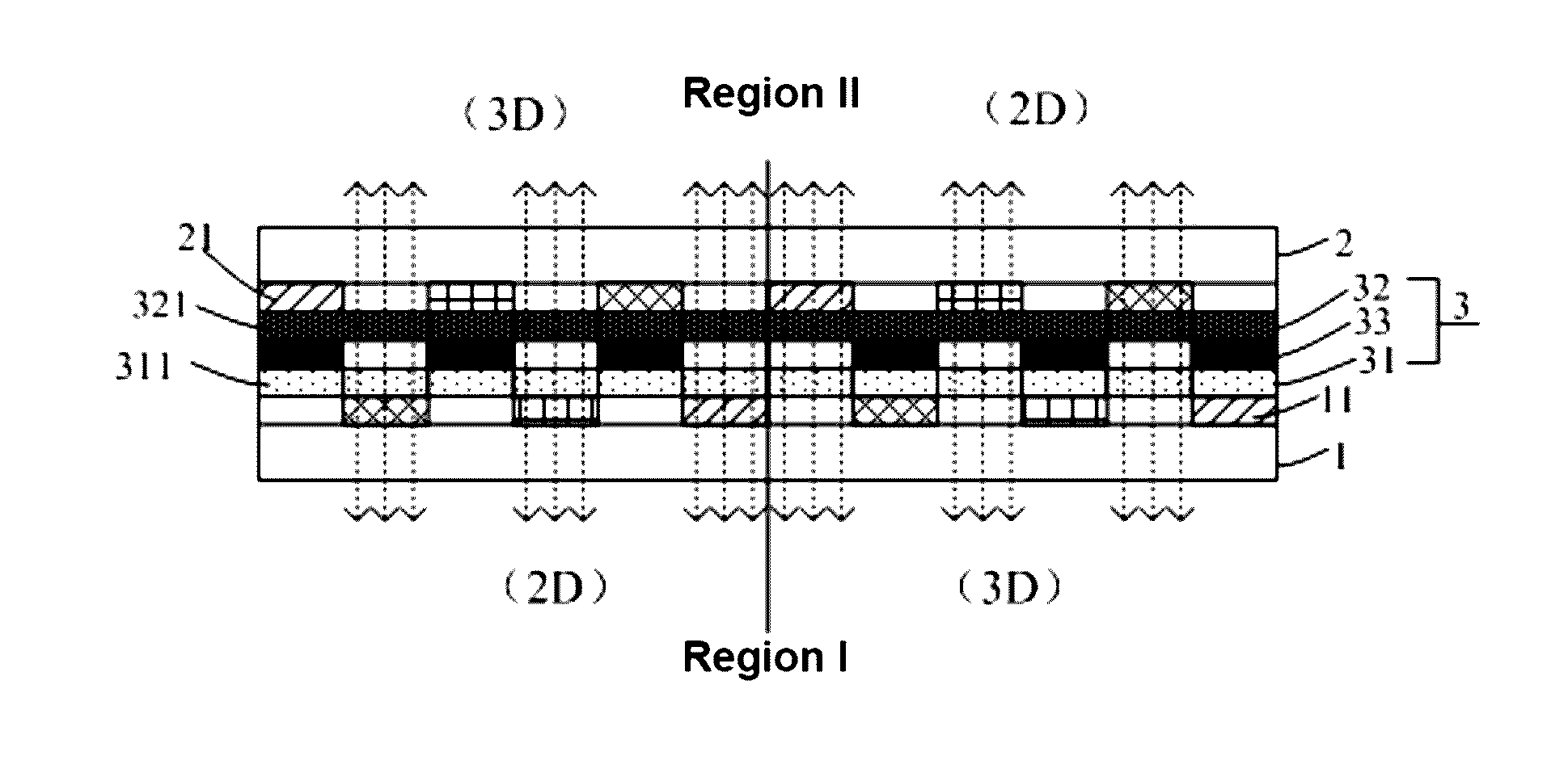
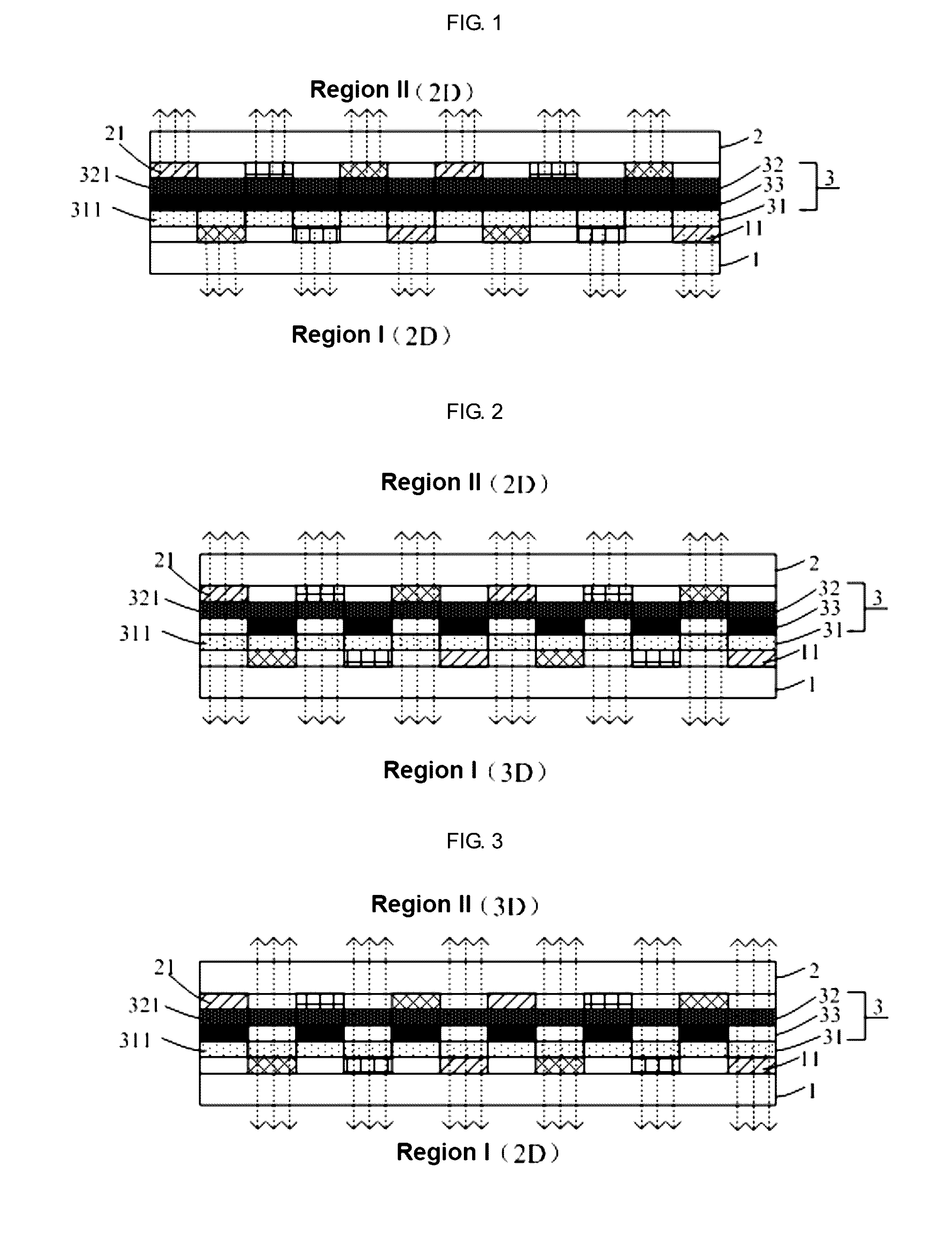
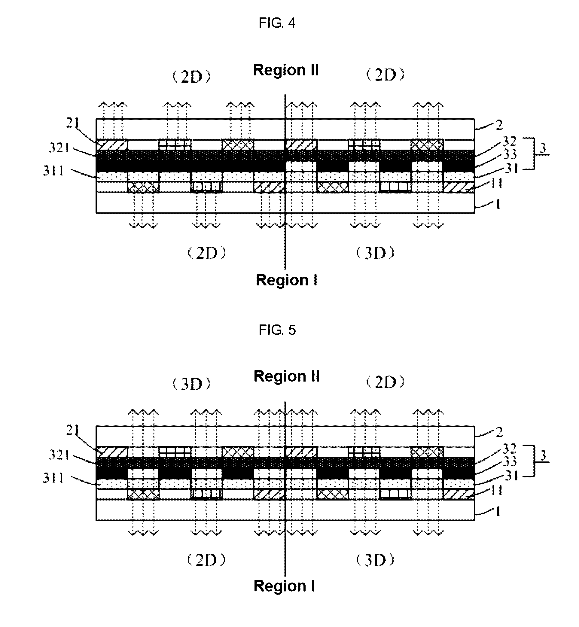
[0036]As shown in FIGS. 1 to 5, the present embodiment provides a display panel including a first substrate 1 and a second substrate 2 which are assembled to form a cell and a control unit (not shown in the figures). The first substrate 1 is provided with a plurality of first light-emitting units 11 which are double-sided light emitting devices thereon, and the second substrate 2 is provided with a plurality of second light-emitting units 21 which are double-sided light emitting devices thereon. The control unit is connected to the plurality of first light-emitting units 11 and the plurality of second light-emitting units 21, and is configured to control the first light-emitting units 11 and the second light-emitting units 21 to emit light or not to emit light, so as to realize single-sided display or double-sided display. The display panel according to the present embodiment further includes a grating-function layer 3 interposed between the first substrate 1 and the second substrat...

embodiment 2

[0067]The present embodiment provides a display device including the display panel according to embodiment 1. Thus, the display device according to the present embodiment can realize single-sided 2D display or double-sided display, and in the double-sided display, each side is capable of realizing 2D display and / or 3D display.

[0068]The display device may be any product or component having a display function, such as a mobile phone, a tablet computer, a television set, a display, a laptop computer, a digital photo frame, a navigator, and the like.

[0069]Of course, the display device according to the present embodiment may include other conventional structures such as a power supply unit, a display driving unit, and the like.


PUM

PropertyMeasurementUnit
electrochromicaaaaaaaaaa
electric fieldaaaaaaaaaa
widthaaaaaaaaaa

Abstract

A display panel comprises a first substrate and a second substrate which are assembled to form a cell and a control unit. The first substrate is provided with a plurality of first light-emitting units which are double-sided light emitting devices thereon, and the second substrate is provided with a plurality of second light-emitting units which are double-sided light emitting devices thereon. The control unit is configured to control the first light-emitting units and the second light-emitting units to emit light or not to emit light. The display panel further comprises a grating-function layer interposed between the first substrate and the second substrate. The grating-function layer comprises controllable light blocking regions and controllable light transmissive regions, and the light blocking regions and the light transmissive regions cooperate with the first light-emitting units and the second light-emitting units to realize single-sided display or double-sided display.

Description

CROSS-REFERENCE TO RELATED APPLICATIONS[0001]The present application claims the priority of Chinese Patent Application No. 201510226623.5, filed on May 6, 2015, the contents of which are incorporated herein in their entirety by reference.FIELD OF THE INVENTION[0002]The present invention relates to the field of display technology, and in particular, relates to a display panel, a display method of the display panel, and a display device.BACKGROUND OF THE INVENTION[0003]An organic light emitting diode (OLED) display panel has obvious advantages, such as self-luminescence, low power consumption, no visual dead angle, fast response, high contrast, and the like, over a liquid crystal display panel, and thus is considered to be the mainstream development trend of future display panels.[0004]At present, most of the OLED display panels on the market mainly realize single-sided display. In many cases (e.g., in cases of digital signage, electronic communication equipment, cash register facilit...

Claims


Application Information

Patent Timeline
Patent Type & Authority Applications(United States)
IPC IPC(8): H01L27/32H01L51/52G02F1/157
CPCH01L27/322H01L51/5203G02F1/157G02B30/27H10K59/00G02F2201/44H10K59/50H10K59/128
Inventor XU, LIYANZHANG, CHUNBING
Owner BOE TECH GRP CO LTD
Learn More