
Linear induction motor plunger lift

a technology of plunger lift and induction motor, which is applied in the direction of fluid removal, earthwork drilling and mining, and wellbore/well accessories, etc., can solve the problems of reducing the output of wells, increasing the loading of wells, and insufficient gas flow rate, so as to reduce the force, less energy consumption, and low maintenance cost

Active Publication Date: 2016-10-27
CONOCOPHILLIPS CO
View PDF3 Cites 13 Cited by
  • Summary
  • Abstract
  • Description
  • Claims
  • Application Information

AI Technical Summary

Benefits of technology

The patent describes a system for converting electrical energy into mechanical energy using plungers and field magnets. This system offers advantages over traditional rotary-to-linear devices, including higher performance, reliability, and automation capabilities. The plungers can be accelerated downhole by reversing the current to the field magnets, reducing the overall pumping time. The system can be designed for different applications, and the topology of the armature and the use of slots or slotless configurations can affect its performance. The technical effects of this system include improved hydrocarbon recovery, reduced friction and drag effects, and improved dynamic performance and servo characteristics.

Problems solved by technology

However, at some point the flow rate of gas will be insufficient to carry liquids out of the well.
As a result, the liquid loading in the well will increase, and liquid will collect in the bottom of the well, further reducing its output.
A well without a deliquification technique will stop flowing or slow down and become a non-productive well, long before a properly deliquified well will.

Method used


Image

  • Linear induction motor plunger lift
  • Linear induction motor plunger lift
  • Linear induction motor plunger lift

Examples


Embodiment Construction

[0044]The disclosure provides one or more of the following embodiments in any combination thereof:[0045]An improved plunger lift system, the plunger lift system having a cased well, a plunger in the cased well moveable from a stop at the bottom of the cased well to a top of the cased well, thus delivering fluids to a wellhead, wherein plunger lift force is provided by a fluid pressure in said well, wherein the improvement comprises replacing said fluid pressure plunger lift force with a linear induction motor (LIM) plunger lift force.[0046]An improved plunger lift system wherein said LIM is a tubular linear induction motor (TLIM).[0047]An improved plunger lift system wherein said LIM also drives the plunger down said tubing at a speed faster than gravity drop speed.[0048]An improved plunger lift system, wherein the plunger lift system having a tubing positioned in a cased well, a plunger in the tubing moveable from the bottom of the tubing to a top of the tubing, wherein plunger lif...


PUM


Abstract

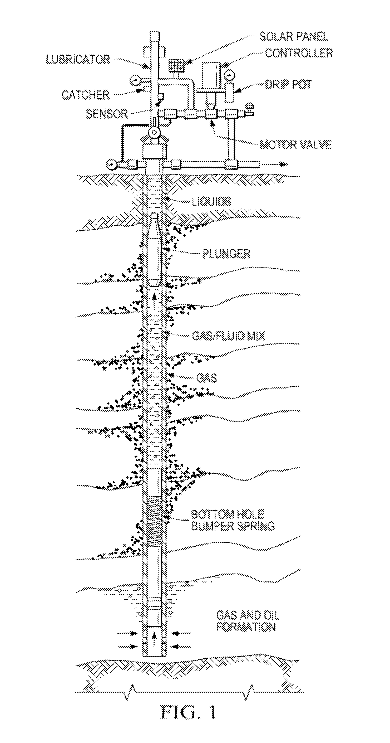
A plunger lift system that uses a linear induction motor instead of gas or fluid pressure to lift the plunger. Electrical voltage is applied to electromagnets installed along the tubing of a wellbore that will induce magnets contained within a special plunger that is introduced inside the tubing to move it and allow it to lift liquids with a piston-like action. The electromotive force may be adjusted by varying the applied voltage as needed to lift the column of liquid from the wellbore or the current reversed to accelerate and optimize plunger descent.

Description

PRIOR RELATED APPLICATIONS[0001]This application is a US Non-provisional Application, which claims the benefit of and priority to U.S. Provisional Application Ser. No. 62 / 108,340 filed Jan. 27, 2015. This application is incorporated herein by reference in its entirety for all purposes.FEDERALLY SPONSORED RESEARCH STATEMENT[0002]Not applicable.FIELD OF THE DISCLOSURE[0003]The disclosure generally relates to an improved plunger lift system based on linear induction principles.BACKGROUND OF THE DISCLOSURE[0004]As natural gas is produced from gas wells, the pressure in the formation will decrease, resulting in a reduction in gas flow rate and associated gas velocity. Before the natural drive pressure is reduced, the flow rate and velocity of produced gas may be sufficient to remove the liquids from the well with the gas. However, at some point the flow rate of gas will be insufficient to carry liquids out of the well. As a result, the liquid loading in the well will increase, and liquid...

Claims


Application Information

Patent Timeline
IPC IPC(8): E21B43/12
CPCE21B43/121E21B43/128
Inventor DECARLO, LEONARD J.
Owner CONOCOPHILLIPS CO
Learn More