Elevator

Active Publication Date: 2016-10-27
KONE CORP
View PDF13 Cites 12 Cited by
  • Summary
  • Abstract
  • Description
  • Claims
  • Application Information

AI Technical Summary

Benefits of technology

The invention is an improved elevator system that can accurately determine the position of the elevator car without using numerous positioning switches. This solution is easy to install and can be used in existing or new elevators, reducing construction time and downtime. The system uses a rope and a guiding means to determine the position of the car, with code marks on the rope and sensors that detect the code marks as the rope moves. An analyzer is used to determine the current position of the car based on the detected code marks. This method ensures accuracy and reliability.

Problems solved by technology

A drawback of these known solutions has been that a very long code pattern needs to be provided and installed accurately in the hoistway during installation process of the elevator.
The installation process is time consuming as it needs to be done very accurately, and majority of the work needs to be performed at the installation site.
Thereby, the installation process postpones completion of the new elevators and increases down time of the elevator being modernized.
In many elevator configurations it is difficult and laborious to fix the component comprising the code mark pattern in such a way that it is continuous and can be reliably sensed.
Particularly, a drawback of known solutions is that the installation of the code mark pattern in the hoistway is challenging to carry out with good results, because the base on which the strip is to be added is difficult to make firm enough and immune to disturbances caused by car movement so that a reliable sensing can be obtained during movement of the car.
Thereby, they are not firm and immune to disturbances, and thus provide a challenging base for the code mark pattern.
Guide rail lines are also prone to deform during use of the elevator, whereby the code pattern is deformed as well.

Method used


Image

  • Elevator
  • Elevator
  • Elevator

Examples


Embodiment Construction

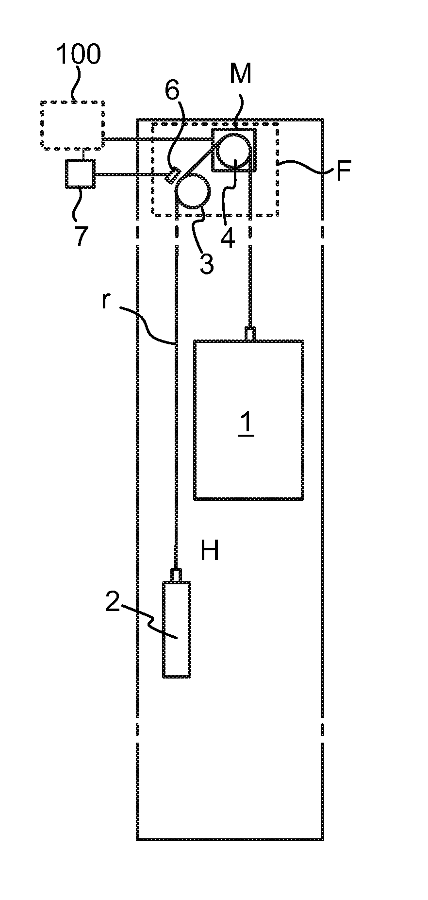
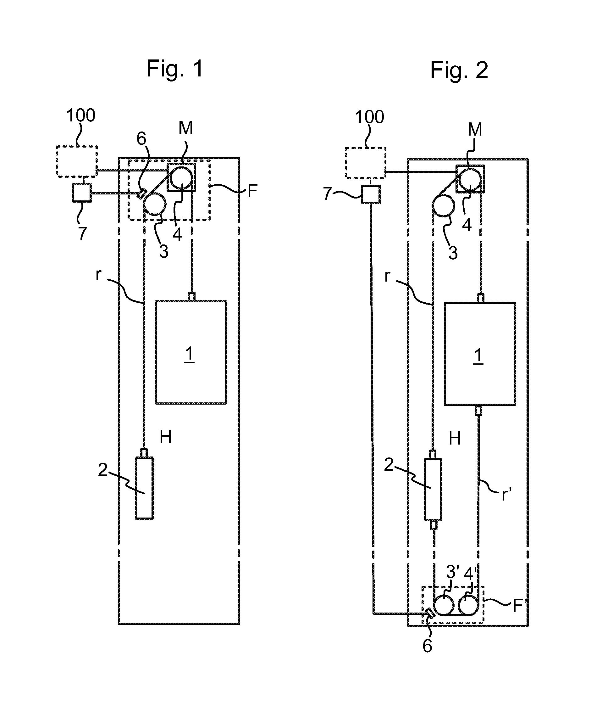
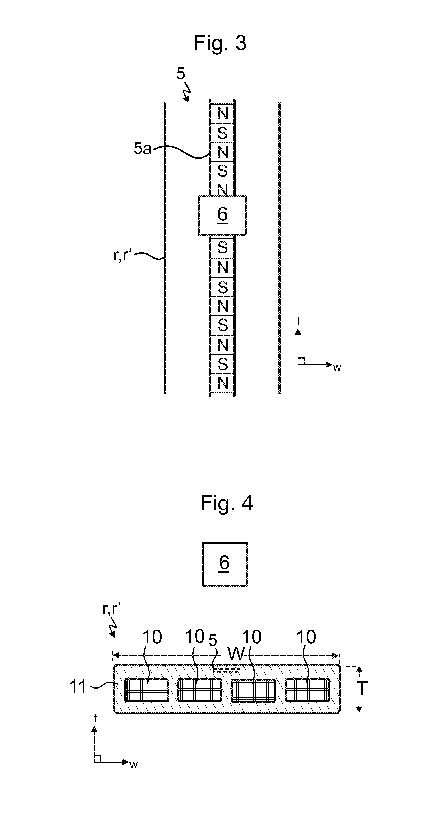
[0046]FIG. 1 illustrates an elevator according to a first preferred embodiment. The elevator comprises a hoistway H, and an elevator car 1 and a counterweight 2 vertically movable in the hoistway H. The car 1 and the counterweight 2 are interconnected by at least one suspension rope r. Thus, each of said the at least one rope r is a suspension rope suspending said car 1 and counterweight 2. The elevator further comprises guiding means 3,4, in the form of one or more rope wheels (here two), for guiding each said rope r along a path. Each said rope r is connected to the elevator car 1, whereby it is movable together with the elevator car 1. For determining current position of the elevator car 1, the elevator is provided with means 5, 5a, 6, 7 for determining position of the elevator car 1. Said means 5, 5a, 6, 7 for determining position of the elevator car 1 comprise an elongated code mark pattern 5 provided on the rope r, which elongated code mark pattern 5 comprises code marks 5a di...


PUM


Abstract

An elevator includes a hoistway; an elevator car vertically movable in the hoistway; a rope connected to the elevator car movably together with the elevator car; a guide for guiding the rope along a path; and a device for determining position of the elevator car. The device for determining position of the elevator car including an elongated code mark pattern provided on the rope, which elongated code mark pattern comprises code marks distributed along the length of the rope; one or more sensors mounted beside the rope for sensing code marks of the code mark pattern; and an analyzer connected with the at least one sensor. The one or more sensors are arranged to sense code marks of the code mark pattern passing by them when the rope moves along its path, and the analyzer is configured to determine current position of the elevator car based on code marks sensed by the one or more sensors during movement of the rope.

Description

FIELD OF THE INVENTION[0001]The invention relates to an elevator for transporting passengers and / or goods, and in particular to determining position of the car thereof.BACKGROUND OF THE INVENTION[0002]In modern elevators, the position of the elevator car needs to be known for various reasons. For example, car position is typically used as a parameter based on which movement of the elevator car is controlled. There are various other uses for car position, such as uses related to safety and destination control algorithms.[0003]In a conventional elevator, separate positioning switches are placed on each floor. These switches can indicate when the car is at their level and thereby position can be determined based on signals from said switches. In addition, elevators having long floor-to-floor—distances are provided with additional switches, so called dummy switches, in express zones that are between floors. This is the case for example with so called express or shuttle elevators.[0004]A...

Claims


Application Information

Patent Timeline
IPC IPC(8): B66B5/00B66B7/06B66B9/00
CPCB66B5/0018B66B9/00B66B7/062B66B1/3492B66B3/023
Inventor PURANEN, MIKKOALASENTIE, PENTTI
Owner KONE CORP
Why Eureka
Try Eureka