
Systems and Methods for Performing High Speed Video Capture and Depth Estimation Using Array Cameras

a technology of array cameras and video capture, applied in the field of digital cameras, can solve the problems of difficult task, fast moving object shape distortion, etc., and achieve the effect of reducing the relative rolling shutter between the cameras, reducing the difficulty of read-out, and reducing the difficulty of task

Active Publication Date: 2016-10-20
FOTONATION LTD +1
View PDF1 Cites 22 Cited by
  • Summary
  • Abstract
  • Description
  • Claims
  • Application Information

AI Technical Summary

Benefits of technology

The invention is about a system and method for capturing high-speed video and estimating depth using multiple cameras. These cameras can have different shutters and can be arranged in an array to capture real-world scenes. The technique for estimating depth and rendering video depends on the number, type, and shutter speed of the cameras. By minimizing the rolling shutter between cameras and aligning them correctly, the system can reduce alignment errors and produce smoother video.

Problems solved by technology

The Wilburn et al. paper disclosed that creating a single high-speed video sequence involves aligning the cameras in the array to a reference viewpoint and notes that this is a difficult task.
Where the assumption does not hold true, the Wilburn et al. paper notes that objects off the focal plane remain sharp but appear to move from frame to frame of the aligned images due to the alignment errors.
When all objects are assumed to be on the same plane, alignment errors result for objects that do not lie on the plane.
The Wilburn et al. paper identifies that a disadvantage of using sensors with rolling shutters for high speed video capture is that the rolling shutter can distort the shape of fast moving objects.

Method used


Image

  • Systems and Methods for Performing High Speed Video Capture and Depth Estimation Using Array Cameras
  • Systems and Methods for Performing High Speed Video Capture and Depth Estimation Using Array Cameras
  • Systems and Methods for Performing High Speed Video Capture and Depth Estimation Using Array Cameras

Examples


Embodiment Construction

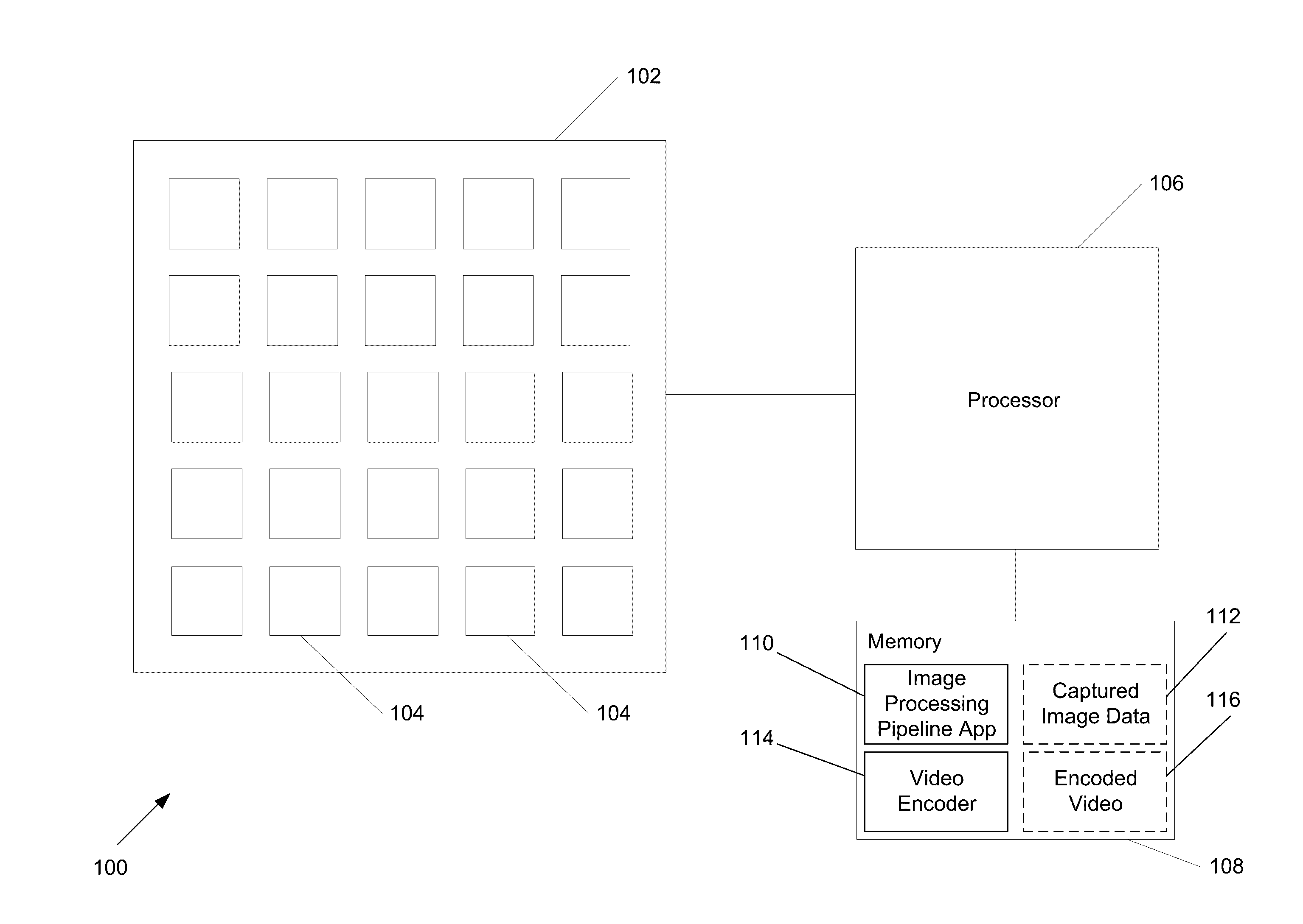
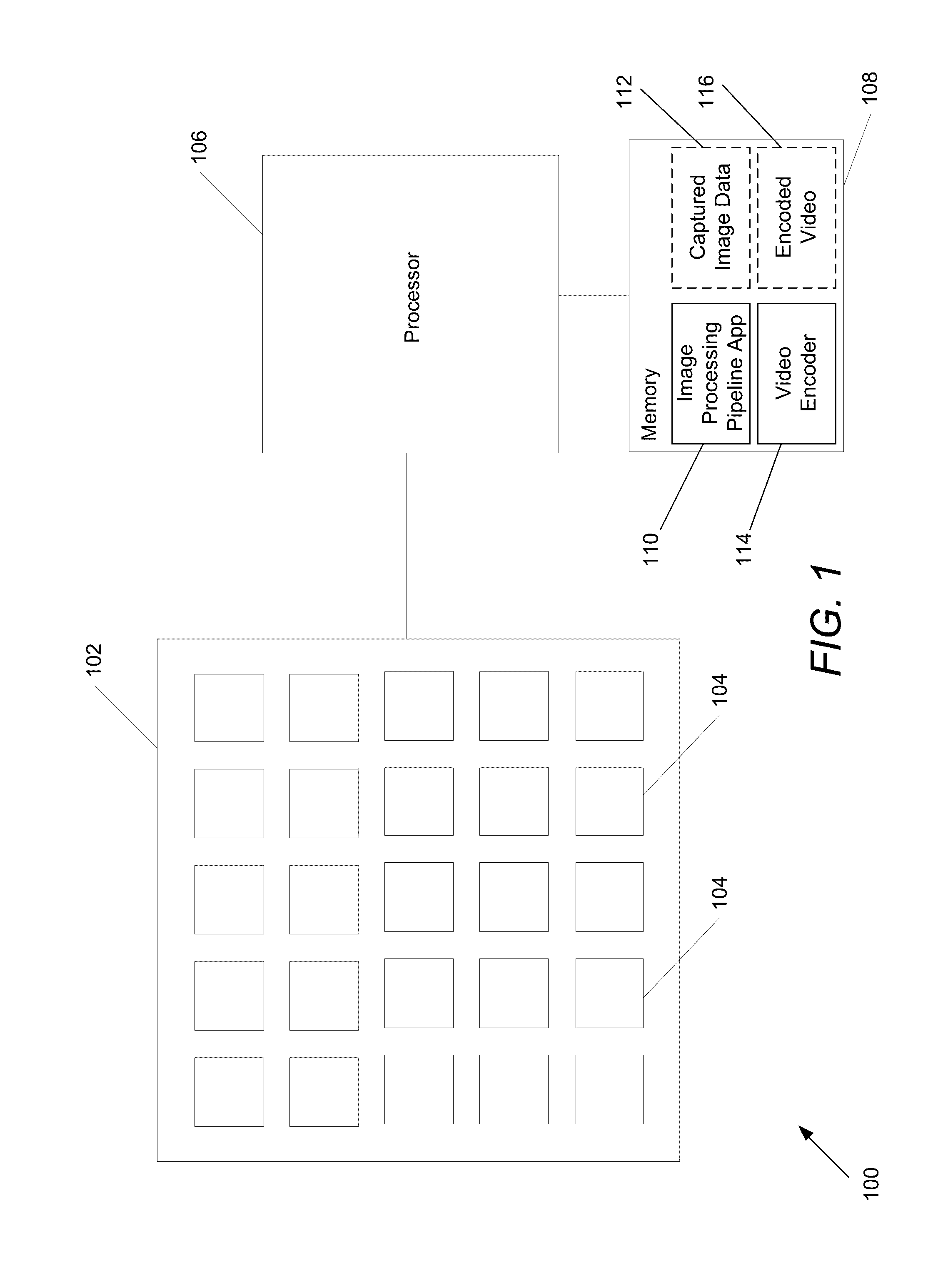
[0049]Turning now to the drawings, systems and methods for rendering high frame rate video sequences using image data captured by different groups of cameras within an array camera in accordance with an embodiment of the invention are illustrated. Video sequences typically have frame rates in the order of 24 frames per second (fps) or 30 fps. A frame rate in excess of 60 fps can be considered to be so-called “high frame rate” video. In the context of the array cameras discussed herein, high frame rate video is considered to be video in which the rate at which frames are rendered is faster than the rolling shutter speed used by the array camera when reading out data from a single camera or group of cameras within the array. By way of example, an array camera may be able to read out image data from each of four groups of cameras at the rate of 30 fps and render a high speed video sequence from the four sets of image data at 120 fps. By appropriately staggering the start times of image...


PUM


Abstract

High speed video capture and depth estimation using array cameras is disclosed. Real world scenes typically include objects located at different distances from a camera. Therefore, estimating depth during video capture by an array camera can result in smoother rendering of video from image data captured of real world scenes. One embodiment of the invention includes cameras that capture images from different viewpoints, and an image processing pipeline application that obtains images from groups of cameras, where each group of cameras starts capturing image data at a staggered start time relative to the other groups of cameras. The application then selects a reference viewpoint and determines scene-dependent geometric corrections that shift pixels captured from an alternate viewpoint to the reference viewpoint by performing disparity searches to identify the disparity at which pixels from the different viewpoints are most similar. The corrections can then be used to render frames of video.

Description

FIELD OF THE INVENTION[0001]The present invention generally relates to digital cameras and more specifically to systems and methods for capturing video and images using array cameras.BACKGROUND[0002]High speed videography using camera arrays has been proposed by Schechtman et al. “Increasing Space-Time Resolution in Video,”European Conference on Computer Vision (ECCV), May 2002 and Wilburn et al. “High-Speed Videography using a Dense Camera Array”IEEE Society Conference on Pattern Recognition, 2004.[0003]The Wilburn et al. paper disclosed that creating a single high-speed video sequence involves aligning the cameras in the array to a reference viewpoint and notes that this is a difficult task. Accordingly, the Wilburn et al. paper proposes using a simplifying assumption that the imaged scene lies within a shallow depth of a single object plane. The Wilburn et al. paper notes that this assumption only holds for scenes that are either relatively flat or sufficiently far from the array...

Claims


Application Information

Patent Timeline
IPC IPC(8): H04N5/232G06T7/00G06T7/60H04N5/225G06T3/40
CPCH04N5/23232H04N5/2258G06T7/0051G06T3/4007G06T7/60H04N5/23293H04N5/2226G06T7/55G06T2207/10052H04N23/45H04N23/951H04N23/63H04N25/531H04N23/843H04N13/00
Inventor VENKATARAMAN, KARTIKHUANG, YUSONGJAIN, ANKITCHATTERJEE, PRIYAM
Owner FOTONATION LTD
Learn More