
View synthesis - panorama

a technology of panorama and view, applied in the field of panorama stitching, can solve the problems of discontinuity at the seam, known parallax problems, and the failure of panoramic video production to achieve the effect of optimizing the panorama stitching of video frames

Inactive Publication Date: 2016-10-20
MAGOR COMM CORP
View PDF9 Cites 21 Cited by
  • Summary
  • Abstract
  • Description
  • Claims
  • Application Information

AI Technical Summary

Benefits of technology

This patent describes a computer system that helps stitch together parts of a panorama or video frames. It can handle large amounts of edge pixels efficiently. The system aligns edges from different images in the overlapping region, making the stitching process more accurate. Overall, this leads to a better user experience when viewing panoramas or videos.

Problems solved by technology

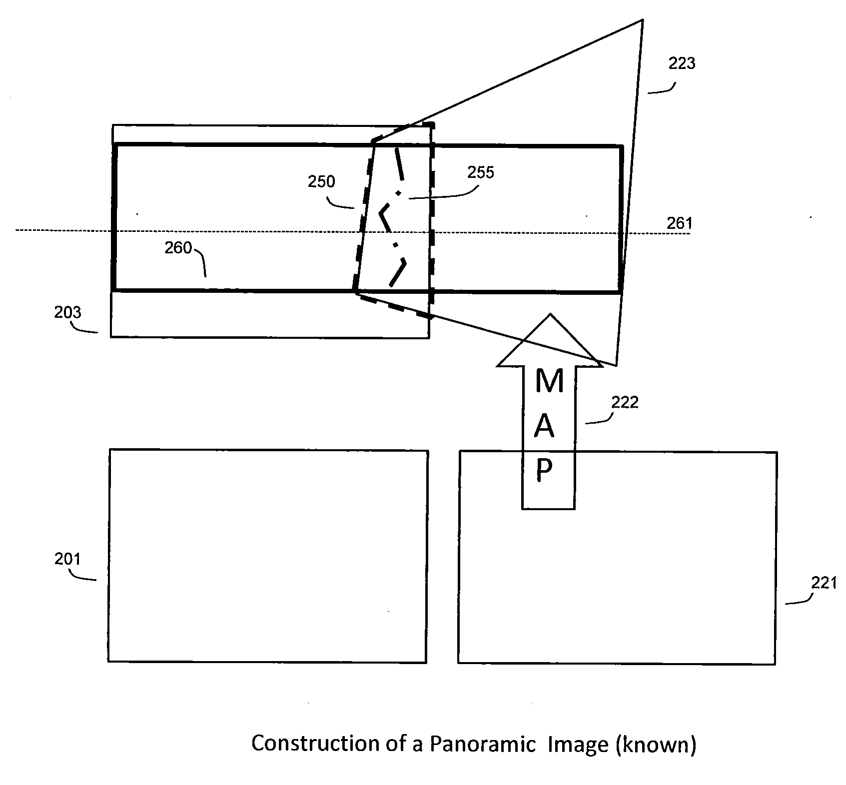
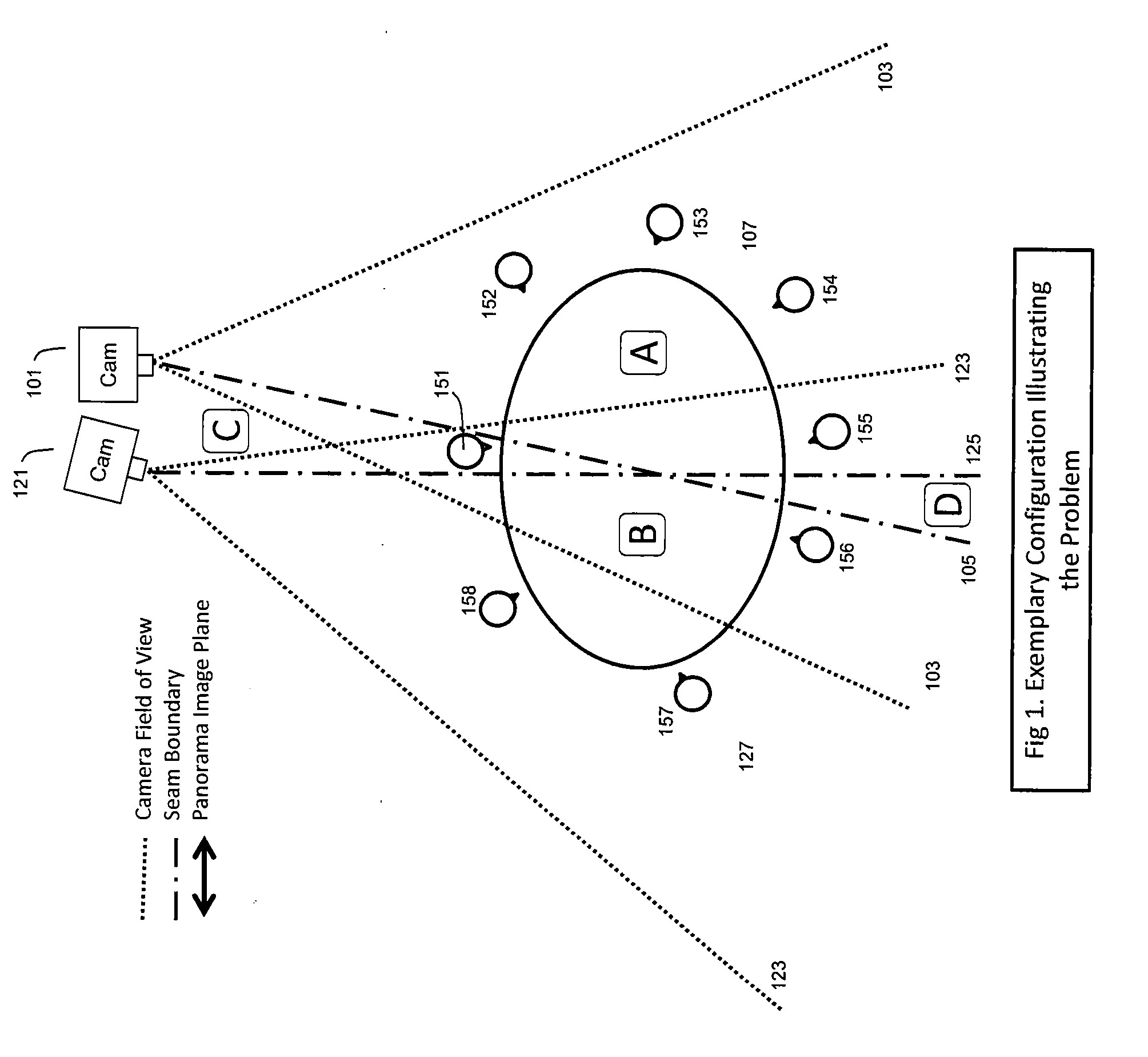
When the distance from a given camera to the nearest object is significantly less than the distance to the furthest object in the scene, known parallax problems arise in constructing the panorama image stream.
Twisting and distortion will lead to discontinuity at the seam.
For the above reasons panoramic video production has been much less successful than still image production.
Techniques such as blurring have been used to hide edge mismatch in an unsatisfactory way and do nothing to address odd shaped tables etc.
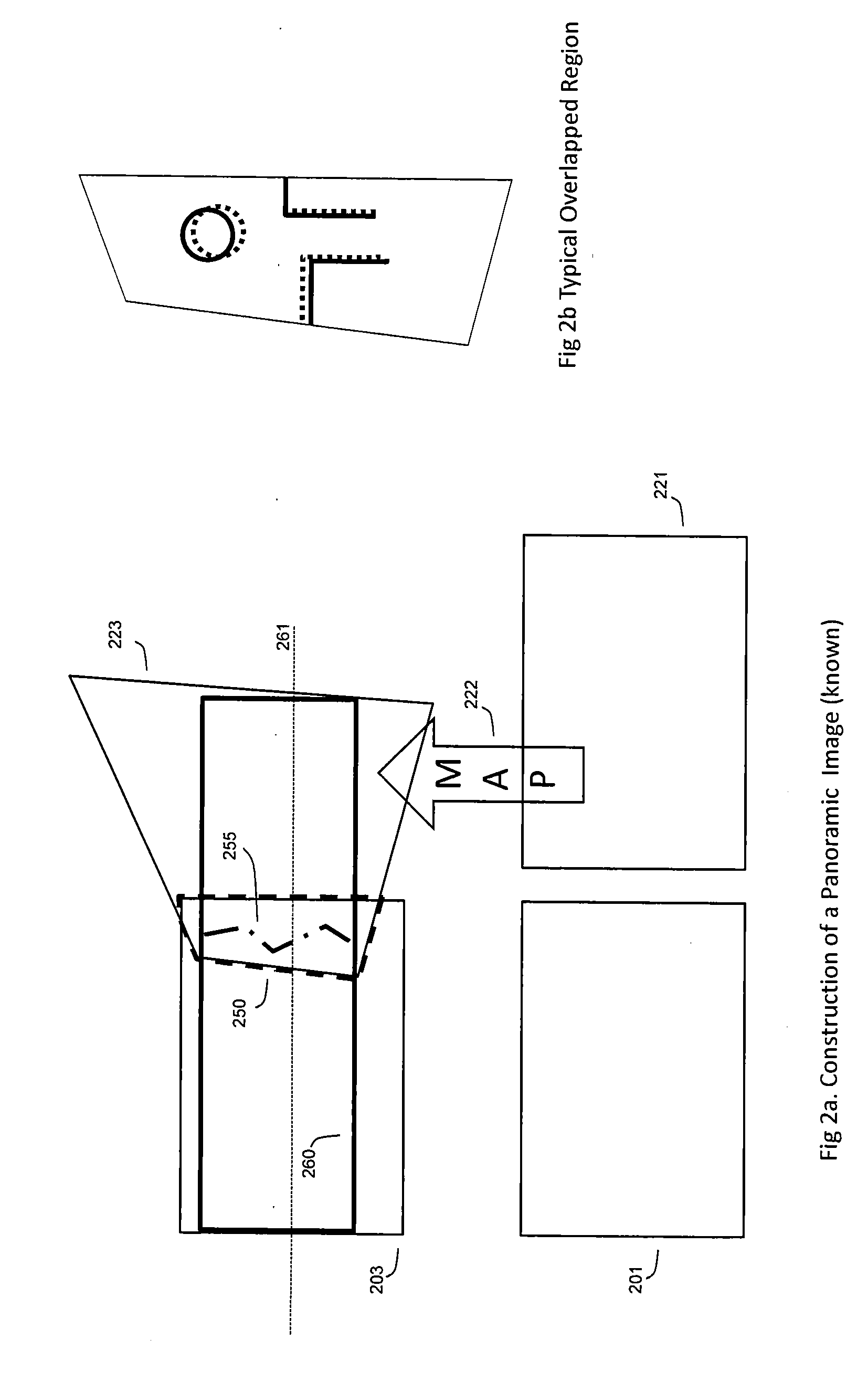
A common problem in the stitching step is the ghosting effect, which is caused by the misalignment between images after transformations.
This misalignment can be caused by errors in the matching step, scaling change, radial distortion from the camera lenses, etc., but mainly because the homography transform itself only favors co-planar scenes (in which most objects approximately lie in the same plane).
Some typical problems exist in both matching and stitching steps.
For the matching step, the complexity of SIFT feature matching is high, making it unsuitable for real-time panorama video applications.
In addition, for some scenes which are mostly composed of un-textured surfaces, there might not be enough matched SIFT features for the estimation of homography transformations.
However, if the misaligned objects cross the overlapping / non-overlapping boundary, it may bring object distortion to the non-overlapping parts of the images.
Both SIFT feature detection and matching are time-consuming and not suited to real time constraints of videoconference production.
Similarly the complexity of RANSAC is also high due to its iterative nature.
But misalignments will mostly likely happen especially when the scene is non-coplanar.
There are some features of CPD which do not make it very suitable for edge matching between the overlapped regions of two panoramic images: CPD could not handle large amount of edge pixels (such as tens of thousands); CPD shifts all pixels even if only a very small part of edge pixels need adjustments; and CPD could not handle partial-to-partial matching in which only part of pixels in one edge group match part of pixels in another edge group.[1] M. Brown and D. G. Lowe, “Automatic Panoramic Image Stitching Using Invariant Features,” International Journal of Computer Vision, vol.

Method used


Image

  • View synthesis - panorama
  • View synthesis - panorama
  • View synthesis - panorama

Examples


Embodiment Construction

[0108]The present invention will be described with respect to particular embodiments and with reference to certain drawings but the invention is not limited thereto but only by the claims. The drawings described are only schematic and are non-limiting. In the drawings, the size of some of the elements may be exaggerated and not drawn to scale for illustrative purposes. The dimensions and the relative dimensions do not correspond to actual reductions to practice of the invention.

[0109]Furthermore, the terms first, second, third and the like in the description and in the claims, are used for distinguishing between similar elements and not necessarily for describing a sequential or chronological order. It is to be understood that the terms so used are interchangeable under appropriate circumstances and that the embodiments of the invention described herein are capable of operation in other sequences than described or illustrated herein.

[0110]It is to be noticed that the term “comprisin...


PUM


Abstract

Disclosed is a computer implemented system that facilitates optimized panoramic stitching, comprising an interface that receives images corresponding to different camera locations. Each image comprises a first image depicting a portion of a scene from the point of view of a first camera location and a second image depicting a portion of a scene from the point of view of a second camera location. There is an overlapping region detection component that detects an overlapping region between the first and second images, a first homography component that transforms the first image to the perspective of the overlapped region of the second image, an edge detection component that partitions and groups all edge pixels in the overlapped region of the first image and the second image according to their connectivity, a first transformation component that transforms each connected edge group in the first image based on initial positions of each edge group after transformation by the first homography component, a second transformation component that transforms each connected edge group in the first image after transformation from the first transformation component, a matching component that matches the transformed edge groups of the first image determined from the second transformation component with the edge pixels of the second image to produce edge matching results, and a second homography component that transforms the first image to the perspective of the second image based on the edge matching results. There is also a merger block which performs stitching to merge the two images together based on the edge matching results and the transformed image from the second homography component. The merger block performs the stitching along a border of the second image that is in the overlapped region, and the first transformation component and the second transformation component apply different transforms.

Description

CROSS-REFERENCE[0001]This application claims the benefit of U.S. Provisional Application 62 / 147,157 filed on Apr. 14, 2015 and incorporated by reference herein.TECHNICAL FIELD OF THE INVENTION[0002]The present invention relates to panorama stitching, and in particular to algorithms that construct a panorama image stream.BACKGROUND OF THE INVENTION[0003]Starting with a sequence of images taken by rotating a camera located on one central point, panorama algorithms try to stitch this sequence of images together to give an extended scene for a kind of immersive experience. This concept is referred to as panorama stitching and is a topic that has been studied in both academia and industry during the past decade. The concept is also applicable to video production. By necessity, production of a video panorama requires multiple cameras. Each camera therefore views the real, three dimensional, scene from a slightly different perspective.[0004]When the distance from a given camera to the near...

Claims


Application Information

Patent Timeline
Patent Type & Authority Applications(United States)
IPC IPC(8): G06T11/60G06K9/46G06K9/62G06T7/00G06V10/44G06V10/75H04N25/00H04N25/42
CPCG06T11/60G06T7/0085G06K9/4604G06K9/6201G06T2207/20221G06T7/0042G06T2207/20021G06K2009/4666G06K9/6267G06T3/4038G06V10/16G06V10/44G06V10/462G06V10/75G06F18/22G06F18/24
Inventor HUANG, XIAODONG
Owner MAGOR COMM CORP
Learn More